Monday, January 26, 2015
Stereo Preamplifier With Bass Boost
This preamplifier was designed to cope with CD players, tuners, tape recorders etc., providing an ac voltage gain of 4, in order to drive less sensitive power amplifiers. As modern Hi-Fi home equipment is frequently fitted with small loudspeaker cabinets, the bass frequency range is rather sacrificed. This circuit features also a bass-boost, in order to overcome this problem. You can use a variable resistor to set the bass-boost from 0 to a maximum of +16dB @ 30Hz. If a fixed, maximum boost value is needed, the variable resistor can be omitted and substituted by a switch.
Stereo Preamplifier With Bass Boost Circuit diagram:
P1 = 10K
P2 = 100K
R1 = 100K
R2 = 100K
R3 = 15K
R4 = 10K
R5 = 22K
R6 = 15K
R7 = 1K
R8 = 470R
C1 = 2.2uF-25v
C2 = 2.2uF-25v
C3 = 470uF-35v
C4 = 1uF-35V
C5 = 2.2uF-25v
C6 = 47nF-63v
C7 = 22uF-25v
IC1 = TL072, Opamp
SW1 = DPST Switch
Notes:
- Schematic shows left channel only, but R1, R2, R3 and C1, C2, C3 are common to both channels.
- For stereo operation P1, P2 (or SW1), R4, R5, R6, R7, R8 and C4, C5, C6, C7 must be doubled.
- Numbers in parentheses show IC1 right channel pin connections.
- A log type for P2 ensures a more linear regulation of bass-boost.
- Needing a simple boost-in boost-out operation, P2 must be omitted and SW1 added as shown in the diagram.
- For stereo operation SW1 must be a DPST type.
- Please note that, using SW1, the boost is on when the switch is open, and off when the switch is closed.
12V Flourescent Lamp Inverter
Fluorescent tubes use far less energy than incandescent lamps and fluorescent tubes last a great deal longer as well. Other advantages are diffuse, glare-free lighting and low heat output. For these reasons, fluorescent lighting is the natural choice in commercial and retail buildings, workshops and factories. For battery-powered lighting, fluorescent lights are also the first choice because of their high efficiency. The main drawback with running fluorescent lights from battery power is that an inverter is required to drive the tubes.
12V Fluorescent Lamp Inverter Circuit diagram:

Fig.1: two switch-mode circuits are involved here: the DC-DC inverter involving IC1, Q1 & Q2 and the fluoro tube driver which converts high voltage DC to AC via IC3 and Q3 & Q4 in a totem-pole circuit.
Inverter efficiency then becomes the major issue. There are many commercial 12V-operated fluorescent lamps available which use 15W and 20W tubes. However, it is rare to see one which drives them to full brilliance. For example, a typical commercial dual 20W fluorescent lamp operating from 12V draws 980mA or 11.8W. Ignoring losses in the fluorescent tube driver itself, it means that each tube is only supplied with 5.9W of power which is considerably less than their 20W rating. So while the lamps do use 20W tubes, the light output is well below par.
Warning:
This circuit generates in excess of 300V DC which could be lethal. Construction should only be attempted by those experimenced with mains-level voltages and safety procedures.
Thursday, November 20, 2014
3 Channel Audio Mixer Circuit

Although the modular Portable Mixer architecture accessible on these web pages has become a hit for abounding amateurs, some correspondents appropriate a abundant simpler device, mainly for bond address signals.
This architecture should fulfil their needs, featuring three inputs with switchable high/low acuteness and abnormal level-control circuits, accouterment aerial afflict margins and low-noise figures, proportional to gain-level settings. Low accepted burning due to a simple, five-transistor circuitry, allows the Mini Mixer to be powered by a accepted 9V PP3 array for abounding hours.
This architecture should fulfil their needs, featuring three inputs with switchable high/low acuteness and abnormal level-control circuits, accouterment aerial afflict margins and low-noise figures, proportional to gain-level settings. Low accepted burning due to a simple, five-transistor circuitry, allows the Mini Mixer to be powered by a accepted 9V PP3 array for abounding hours.
X Ray Protector Circuits
A protector system that is applied at the beginning of the television technique, therefore most often found on old aircraft models. If the high voltage anode of the picture tube flyback tranfo exceed the permitted limit, the picture tube can generate x-rays from the anode and shadowmask are bombarded by electrons at high speed. To avoid this problem then mounted x-ray surge protector circuit , which automatically "horizontal section will be turned off" if the high voltage from the flyback over.
| X-Ray vertical protect |
The workings of x-ray protector:
- High voltage flyback sampled (generally taken from the pin-heater), rectified and is derived using a divider (devider) that uses a resistor-type high-precision resistor. Sample voltage is used to determine whether the condition is normal flyback voltage or over.
- A "zener diode" as a voltage sensor connected to the sample. In normal conditions the amount of the sample voltage is below the zener voltage of diode so that the condition "off" or is not transparent.
- Suppose there is a sudden event increased flyback voltage - the voltage will rise above the sample diode voltage value, which causes the diode "on" or voltage through the diode, which would trigger protectionist active work.
Problems that can lead to x-ray active protector works:
- Damage that causes the power supply voltage B + or incorrect adjustment over
- Resonant capacitor to the collector of transistor HOT off the decline or solder
- Tranfo replacement flyback mounted do not match.
- Damage to one part in the sensor circuit protectors x-ray alone
| X-ray Protect Circuit |
230 400 Watt Power Amplifier MOSFET
Amplifier circuit below is a series of amplifiers with the amplifier transistor and mosfet. This amplifier output power ranging from 230W up to 400W.
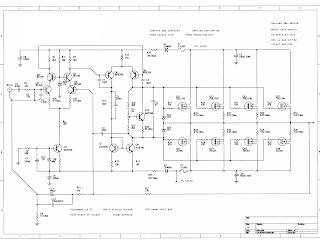 |
| 230 - 400 Watt Power Amplifier |
Egg incubator comtrol list Program
List Program Temperature Controller AT89C2051 egg incubator is a program used to control the temperature control device incubator Egg With AT89C2051 which details a series of articles exist on Temperature Controller With AT89C2051. Many requests are asking for the program lists a series Temperature Controller AT89C2051 egg incubators. Hopefully with the upload list of programs from a series Temperature Controller AT89C2051 egg incubators can help and give inspiration to all who are looking teman2 reference to the construction of the Temperature Controller egg incubators. Temperature Controller program listings AT89C2051 Egg incubators that I uploaded are still many shortcomings, so it can be developed more to get better. Following the program listings.
List Program Temperature Controller AT89C2051 Egg incubators
ORG 0h
Coma EQU 30h
UNIT EQU 31H
Dozens EQU 32H
HUNDREDS EQU 33H
MENU_OK EQU 34H
D_SETING1 EQU 35H
D_SETING2 EQU 36H
D_DISPLAY1 EQU 37H
D_DISPLAY2 EQU 38H
D_TEMPERATURE1 EQU 39H
EQU D_TEMPERATURE2 3AH
REVERSE EQU 3BH
REST EQU 3CH
T_MENU BIT P3.0
T_DOWN BIT P3.1
T_UP BIT P3.2
LAMP BIT P3.3
P_TEMPERATURE BIT P3.4
P_ZX BIT P3.5
ACALL SET_AWAL
START: ACALL TEMPERATURE
ACALL MENU
ACALL APPEAL
ACALL CONVERSION
JMP START
TEMPERATURE: MOV R3, # 64H
MOV TMOD, # 15H
MOV TL0, # 00H
MOV TH0, # 00H
SETB TR0
AGAIN: MOV TL1, # 0EFH
MOV TH1, # 0D8H
SETB TR1
ACALL CONVERSION
WAIT: JNB TF1, WAIT
CLR TR1
CLR TF1
DJNZ R3, AGAIN
CLR TR0
CLR TF0
END_T: MOV D_TEMPERATURE1, TL0
MOV D_TEMPERATURE2, TH0
MOV D_DISPLAY1, D_TEMPERATURE1
MOV D_DISPLAY2, D_TEMPERATURE2
ACALL CONVERSION
END_TEMPERATURE: RET
MENU: JB T_MENU, CHECKING_MENU
ACALL DELAYT
ACALL DELAYT
MOV A, MENU_OK
CJNE A, # 0h, SETING_OK
MENU_OK MOV, # 1H
JMP UP
SETING_OK: MOV MENU_OK, # 0h
JMP END_MENU
UP: JB T_UP, DOWN
MOV A, MENU_OK
CJNE A, # 1H, MENU
ACALL DELAYT
D_SETING1 INC.
MOV D_DISPLAY1, D_SETING1
MOV D_DISPLAY2, D_SETING2
ACALL CONVERSION
MOV A, D_SETING1
CJNE A, # 0FFH, UP
CLR D_SETING1
D_SETING2 INC.
MOV D_DISPLAY1, D_SETING1
MOV D_DISPLAY2, D_SETING2
ACALL CONVERSION
DOWN: JB T_DOWN, MENU
MOV A, MENU_OK
CJNE A, # 1H, MENU
ACALL DELAYT
MOV A, D_SETING1
CJNE A, # 00D, less_LSB
MOV A, D_SETING2
CJNE A, # 00D, less_MSB
JMP MENU
less_LSB: DEC D_SETING1
MOV D_DISPLAY1, D_SETING1
MOV D_DISPLAY2, D_SETING2
ACALL CONVERSION
JMP DOWN
less_MSB: DEC D_SETING2
MOV D_SETING1, # 0FFH
MOV A, D_SETING1
DA A
MOV D_DISPLAY1, D_SETING1
MOV D_DISPLAY2, D_SETING2
ACALL CONVERSION
JMP DOWN
CHECKING_MENU: MOV A, MENU_OK
CJNE A, # 0h, SETTINGS
JMP END_MENU
SETTINGS: MOV D_DISPLAY1, D_SETING1
MOV D_DISPLAY2, D_SETING2
ACALL CONVERSION
JMP UP
END_MENU: RET
APPEAL: MOV A, D_SETING1
CJNE A, D_TEMPERATURE1, CHECKING1
JMP B_MSB
CHECKING1: SubB A, D_TEMPERATURE1
JC B_MSB
JMP LIFE
B_MSB: MOV A, D_SETING2
CJNE A, D_TEMPERATURE2, CHECKING2
JMP STOP
CHECKING2: SubB A, D_TEMPERATURE2
JC SWITCH
JMP END_B
SWITCH: SETB LAMPS
END_B: RET
CONVERSION: MOV R1, D_DISPLAY2; MSByte
MOV R2, D_DISPLAY1; LSByte
MOV R4, # 00D
MOV R5, # 00D
MOV R6, # 00D
MOV R7, # 00D
MOV B, # 10D
MOV A, R2
DIV AB
MOV R4, B; 7,6,5,4 BCD DATA IS
MOV B, # 10
DIV AB
MOV R5, B
MOV R6, A
CJNE R1, # 0h, HIGH_BYTE; CHECK FOR HIGH BYTE
SJMP END_KONVERSI
HIGH_BYTE: MOV A, # 6
ADD A, R4
MOV B, # 10
DIV AB
MOV R4, B
ADD A, # 5
ADD A, R5
MOV B, # 10
DIV AB
MOV R5, B
ADD A, # 2
ADD A, R6
MOV B, # 10
DIV AB
MOV R6, B
ADD A, R7
DA A
MOV R7, A
DJNZ R1, HIGH_BYTE
END_KONVERSI: MOV coma, R4
MOV UNITS, R5
MOV tens, R6
HUNDREDS MOV, R7
ACALL DISPLAY
RET
DISPLAY: MOV A, coma; Segment 1
ADD A, # 10H
SWAP A
MOV P1, A
ACALL DELAY
MOV A, UNIT; Segment 2
ADD A, # 20h
SWAP A
MOV P1, A
ACALL DELAY
MOV A, tens; Segment 3
ADD A, # 40H
SWAP A
MOV P1, A
ACALL DELAY
MOV A, HUNDREDS; SEGMENT 4
CJNE A, # 0h, CONTINUES
MOV A, # 0FH
KEEP: ADD A, # 80h
SWAP A
MOV P1, A
ACALL DELAY
RET
SET_START: MOV MENU_OK, # 0h; 1 = MENU, 0 = OK
MOV D_SETING1, # 0h
MOV D_SETING2, # 0h
MOV D_DISPLAY1, # 0h
MOV D_DISPLAY2, # 0h
RET
DELAY: MOV 42H, # 2H
LAGI_1: MOV 43H, # 0FAH
LAGI_2: DJNZ 43H, LAGI_2
DJNZ 42H, LAGI_1
RET
DELAYT: MOV 42H, # 0A0H
AGAIN_3: MOV 43H, # 0F0H
AGAIN_4: DJNZ 43H, AGAIN_4
DJNZ 42H, LAGI_3
RET
END
Hopefully useful and can help or give an idea of making a program to control temperature egg incubators using the microcontroller

Subscribe to:
Posts (Atom)