Showing posts with label x. Show all posts
Showing posts with label x. Show all posts
Thursday, November 20, 2014
X Ray Protector Circuits
A protector system that is applied at the beginning of the television technique, therefore most often found on old aircraft models. If the high voltage anode of the picture tube flyback tranfo exceed the permitted limit, the picture tube can generate x-rays from the anode and shadowmask are bombarded by electrons at high speed. To avoid this problem then mounted x-ray surge protector circuit , which automatically "horizontal section will be turned off" if the high voltage from the flyback over.
| X-Ray vertical protect |
The workings of x-ray protector:
- High voltage flyback sampled (generally taken from the pin-heater), rectified and is derived using a divider (devider) that uses a resistor-type high-precision resistor. Sample voltage is used to determine whether the condition is normal flyback voltage or over.
- A "zener diode" as a voltage sensor connected to the sample. In normal conditions the amount of the sample voltage is below the zener voltage of diode so that the condition "off" or is not transparent.
- Suppose there is a sudden event increased flyback voltage - the voltage will rise above the sample diode voltage value, which causes the diode "on" or voltage through the diode, which would trigger protectionist active work.
Problems that can lead to x-ray active protector works:
- Damage that causes the power supply voltage B + or incorrect adjustment over
- Resonant capacitor to the collector of transistor HOT off the decline or solder
- Tranfo replacement flyback mounted do not match.
- Damage to one part in the sensor circuit protectors x-ray alone
| X-ray Protect Circuit |
Monday, September 15, 2014
2 X 50W ICs amplifier with STK4191
The above is a stereo amplifier circuit based on IC STK4191 with 2 X 50Watt output power 8 ohm impedance. And besides that you can use some of the IC can also be applied in this series include the STK4101, 4111, 4121, 5131, 4141, 4151, 5161, 4171, 4181, and 4191. Required supply voltage from 12 Volt to 35 Volt DC.
Friday, September 12, 2014
Configuring Xbee with X CTU

In my first look to XBee module it was a little bit confusing to me how to configure this module. Though it looks hard first look after a short period googling but soon I felt that it isnt so hard as I thought.Xbee is now introducing as a wireless solution very quickly. Many integrated features,ease of use makes it a popular device. In this post I will show how to configure a XBee module as coordinator or router using X-CTU software(This software is provided by manufacturer to program the XBee as per need).
Suppose we want to configure a XBee module as router.First we need to make connections with PC.Xbee is 20 pin module looks like

We need only 4 pin
| Pin No. | Name(s) | Description |
| 1 | VCC | 3.3 V power supply |
| 2 | DOUT | Data Out (TX) |
| 3 | DIN | Data In (RX) |
| 10 | GND | Ground |

We need 4 pin from the usb to serial module.
| Pin | Name(s) | Description |
| 1 | VCC | 3.3 V power out |
| 2 | Rx | Data recieve |
| 3 | Tx | Data transfer |
| 4 | GND | Ground |
Next give the connections as required
| XBee | connect with | Usb to serial module |
| VCC | <—> | VCC |
| DOUT | <—> | Rx |
| DIN | <—> | Tx |
| GND | <—> | GND |

Now you are prepared to connect the XBee with X-CTU software. Connect the module with your PC. It will create a serial port in PC. In my case it was COM12.
Open the X-CTU software.It will show the serial port. Click Test/Query button.

It will show the XBee model and serial number if you connect properly.
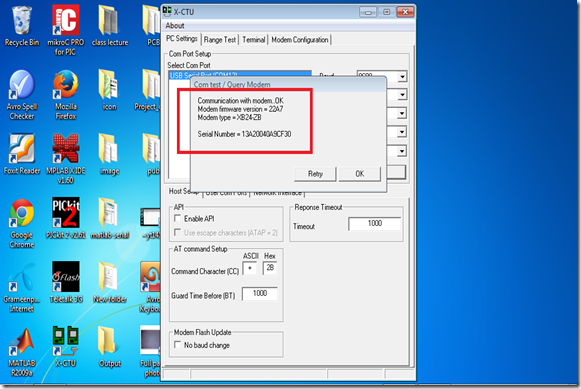
Look at the serial number . It is important because you have to give this number in software later, so save it somewhere else. Click OK.
During my first try I made mistake in connection. So it shows
So if you see this message don’t be afraid,check the connection,may be there is a silly mistake somewhere.
Then go to modem configuration(these button stays at the top menu of the software).Click Read Button.Then it will show the parameters of your Xbee module.

Now it is time to configure it as a coordinator or router. Here we configured as router.
Choose the function set as ZIGBEE ROUTER AT.
Choose a PAN ID between 0000 to FFFF. Here I choose 2001.
Next give Destination Address High and Destination Address Low from the serial number. My XBee module serial no. was 0013A20040A9CF4E. So I set Destination Address High as 0013A200.
Then I set Destination Address Low as 40A9CF4E.
Then click the read button. And you are done.

Tuesday, September 9, 2014
TDA1556Q 2 x 22 W stereo BTL differential amplifier with speaker protection
FEATURES
Few peripheral components
High output power
Low output offset voltage
Fixed gain
Loudspeaker protection (with diagnostic facility)
Differential inputs
Dynamic Distortion Detector (DDD)
High common mode input signal
Very high CMRR
Good ripple rejection
Mute/stand-by switch
Load dump protection
Short-circuit safe
Thermally protected
Reverse polarity safe
High energy handling capability at the outputs (VP = 0 V)
Electrostatic discharge protection
No switch-on/switch-off plop
Flexible leads
Low thermal resistance
GENERAL DESCRIPTION
TDA1556Q is a monolithic integrated class-B output amplifier containing two 22 Watt amplifiers in a BTL configuration. The device is contained in a 17-lead single-in-line (SIL) plastic power package. It has two differential inputs and is primarily intended for car booster applications.
Circuit Diagram:
 |
| Circuit diagram for TDA1556Q 2 x 22 W stereo BTL differential amplifier with speaker protection |
Sunday, August 31, 2014
TDA7566 4 x 40 W multifunction quad power amplifier
Features
- DMOS power output
- High output power capability 4 x 25 W/4 @
- 14.4 V, 1 kHz, 10 % THD, 4 x 40 W max. power
- Max. output power 4 x 60 W/2
- Full I2C bus driving:
- Standby
- Independent front/rear soft play/mute
- Selectable gain 26 dB - 12 dB
- I2C bus digital diagnostics
- Full fault protection
- DC offset detection
- Four independent short circuit protection
- Clipping detector pin with selectable threshold (1%, 10%)
- ESD protection
Description
The TDA7566 is a new BCD technology quad bridge type of car radio amplifier in Flexiwatt25 package specially intended for car radio applications. Thanks to the DMOS output stage the TDA7566 has a very low distortion allowing a clear powerful sound. This device is equipped with a full diagnostics array that communicates the status of each speaker through the I2C bus.The possibility to control the configuration and behavior of the device by means of the I2C bus makes TDA7566 a very flexible product.
Circuit Diagram:
Circuit Diagram:
 |
| TDA7566 - 4 x 40 W multifunction quad power amplifier |
Subscribe to:
Posts (Atom)