Sunday, August 24, 2014
A Charge Pump Wiring diagram Schematic
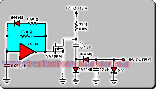
A charge pump is a kind of DC to DC converter that uses capacitors as energy storage elements to create either a higher or lower voltage power source.This is a Positive input and negative output charge pump. The 74Cl4 IC is a self-oscillating driver for the MOSFET power switch.
A Charge Pump Circuit Diagram

It produces a pulse width of 6.5 p,s at a repetition frequency of 100 kHz. When the MOSFET device is off, capacitor C is charged to the positive supply. When the power through the MOSFET switches on, C delivers a negative voltage through the series diode to the output. The zener serves as a dissipative regulator. Because the MOSFET switches fast, operation at high frequencies allows the capacitors in the system to be small.
Subscribe to:
Post Comments (Atom)
No comments:
Post a Comment