Wednesday, October 15, 2014
Build an Alarm Control Keypad Circuit Diagram
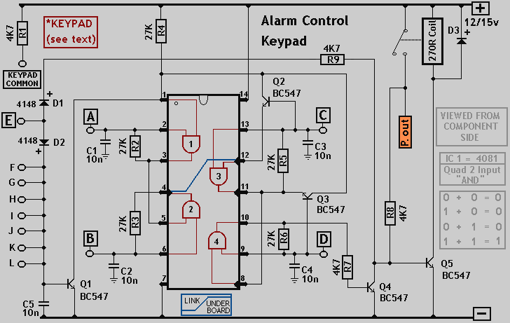

Wednesday, September 17, 2014
Digital Counter with an Interval of Kilometers
The circuit has been designed for a person who loves to jog or walk while measuring the distance that have been covered during the activity.
- 4093 – a quad 2-input NAND with Schmitt trigger inputs integrated circuit, generally characterized by small fluctuation in voltage supply, very high impedance, outputs that can sink and source, one output can drive up to 50 inputs, high speed gate propagation time, high frequency, and low power consumption.
- 4026 – a decade counter where the count advances as the clock input becomes high and has a maximum current of about 1 mA with a 4.5 V supply and 4 mA with a 9 V supply, which can light the appropriate segments of a common cathode 7-segment display.
- 4024 – a ripple counter with glitches that may occur in any logic state systems connected to its outputs due to the slight delay before the later counter outputs respond to a clock pulse; the count advances as the clock input becomes low on the falling edge as indicated by the bar over the clock label that is the usual behavior of the ripple counters which means a counter output can directly drive the clock input of the next counter in a chain.
The whole circuit may be placed in a small box and be placed in pants’ pocket where the 7-segment digital display shows the most significant digit D2 in the leftmost portion where it shows the 0 to 9 Km digits. The dot in between is always ON to segregate KM form hm. The least significant digit D1 is displayed at the rightmost part where it illustrates hundreds of meters and the dot is illuminating after every 50 meters of walking. In every two steps, a beeper will signal each count of unit, although it is not included in this circuit.
Circuit diagram :

Digital Counter with an Interval of Kilometers Circuit Diagram
A length of 78 centimeters is the calculated measure of a normal step which causes the LED to illuminate after 64 steps to signal a 50 meter distance. For a mercury switch, the illumination occurs every 32 steps. After 128 steps, the display will indicate 100 meters and so on. The SPST push button switch P2 is pressed only upon request in case of low battery consumption. Both push button switches P1 & P2 should be pressed together to reset the circuit in order to prevent accidental reset of the counters. The circuit should be considered as an approximation and not as a precision meter because it is very difficult to obtain the correct position of the mercury switch SW1 in the box where the degree of slope is being set.
The excessive bouncing of mercury switch is provided with certain degree of tolerance from the monostable multivibrator consisting of IC1A & IC1B. IC2 therefore is divided by 64 as a clean square pulse enters. The LED dot segment of D1 is driven by Q2 for every 32 pulses counted by IC2. At each monostable count, an audio frequency square is generated by IC1C for a short time. Using SW2 will disable the beep while the piezo sounder is driven by Q1. The power of beeper sound can be adjusted by trimming the value of R6. SW3 can be omitted when the display is disabled resulting to negligible current consumption.
The digital step counter circuit is widely used by people as their motion monitor while walking or jogging and other most ideal exercise possible. Some designs may come with a digital clock and backlight for easy reading during running, and belt clips.
Saturday, September 6, 2014
How to make an electric magnet
This is for kids
This is so simple thing.you need following things first
1 A nail
2 A coil
3A battery
4A switch
Then turn the coil around the nail but before turning the coil cover the nail with a peace of paper.Then attach every thing according to the following schema.finally give the power and close it to the metal dust then you can see they stick to the nail..
# Now you know how to make an electric magnet
# As your second project make an electric bell