Showing posts with label circuit. Show all posts

Thursday, November 20, 2014

3 Channel Audio Mixer Circuit


Although the modular Portable Mixer architecture accessible on these web pages has become a hit for abounding amateurs, some correspondents appropriate a abundant simpler device, mainly for bond address signals.

This architecture should fulfil their needs, featuring three inputs with switchable high/low acuteness and abnormal level-control circuits, accouterment aerial afflict margins and low-noise figures, proportional to gain-level settings. Low accepted burning due to a simple, five-transistor circuitry, allows the Mini Mixer to be powered by a accepted 9V PP3 array for abounding hours.
Read More..

Wednesday, November 19, 2014

Simple Stabilizer Circuit Diagram

SimpleSimple Stabilizer Circuit Diagram

A aerial affection ability accumulation with a continuously capricious stabilised achievement adjustable at any amount amid 0 and 30VDC. The ambit additionally incorporates an cyberbanking achievement accepted limiter that finer controls the achievement accepted from a few milliamperes (2 mA) to the best achievement of three amperes that the ambit can deliver.

This affection makes this ability accumulation basal in the experimenters class as it is accessible to absolute the accepted to the archetypal best that a ambit beneath analysis may require, and ability it up then, after any abhorrence that it may be damaged if article goes wrong. There is additionally a beheld adumbration that the accepted limiter is in operation so that you can see at a glance that your ambit is beyond or not its preset limits.

Read More..

Automatic Water Pump Controller Circuit

Automatic water pump controller is a series of functions to control the Automatic Water Pump Controller Circuit in a reservoir or water storage. As the water level sensor made with a metal plate mounted on the reservoir or water tank, with a sensor in the short to create the top level and a detection sensor for detecting long again made the lower level and ground lines connected to the bottom of reservoirs or reservoir. The series of automatic water pump controller is designed with 2 inputs NOR by 4 pieces and relay that is activated by the transistor. Automatic water pump circuit requires +12 VDC voltage source and can be used to control the water pump is connected to AC power . Here is the complete series of pictures.

Series Automatic Water Pump Controller 


List Component Automatic Water Pump Controller 
R1 = 15K 
R2 = 15K 
R3 = 10K 
R4 = 1K 
D1 = LED 
D2 = 1N4148 
Q1 = BC337 
IC1 = 4001 
SW = SPDT Switches 
Relay RL1 = 12V 

The working principle series of automatic water pump controller above is. At the time the water level is below both sensors, the output IC1C (pin 10) will be LOW, Kemudin when the water began to touch the lower level sensor, the output IC1C (pin10) remains LOW until the water touches the sensor level above, then the output IC1C (pin 10) going HIGH and active relay through Q1 and turn on the water pump to meguras reservoir. At the muli down and water level sensors for water untouched MKA IC1C output (pin 10) remains HIGH until the new water untouched semuasensor IC1C output (pin 10) LOW and water pump died. The series of automatic water pump controller is equipped with SW1 which serves to reverse the logic of drains (the output of IC1C) and the concept of water supplied (output dri IC1D). When SW1 is connected to IC1D the water pump will turn on when the water does not touch all the sensors and will die when all the sensors tesentuh water. Automatic water pump controller can be used to fill or drain the water according to which mode is selected via SW1.
Read More..

Tuesday, November 18, 2014

12VDC to 220V AC 500W Inverter Circuit

Circuit Inverter 500 Watt 12VDC to 220VAC is made using a transistor.
The basiccally of the circuit Inverter 12VDC to 220VAC 500 Watt This is a configuration of 2 pieces of transistors Q1 and Q2 which form a series of Flip-Flop. The output of the flip-flop Q1 and Q2 in the circuit Inverter 12VDC to 220VAC 500 Watt is then broken down for each pulse to complement each other using a series compiled by Q3 and Q4. Output which complement each other is then given to the driver transistors Q5 and Q6 form the transistor 2SC1061. Series Inverter Power Inverter from 12VDC to 220VAC 500 Watt This is a series of parallel transistors Q7 and Q8 are prepared and Q7x and Q8x the form of power with a type 2N3055 transistor 10 pieces. drawing a complete range of circuit Inverter 12VDC to 220VAC 500 Watts can be seen as follows.

12VDC

Step up part of the Circuit Inverter 12VDC to 220VAC 500 Watt 12V CT uses 12V transformer in the secondary and primary 0 - 220V. Working frequency of the Circuit Inverter 12VDC to 220VAC 500 Watt is determined by the flip-flop which is set to 50 Hz.
Read More..

Monday, November 17, 2014

Pulse generator circuit with Logic Gate

Pulse generator circuit above is a pulse generator that uses logic gates. There are so many types and variations that can generate a series of pulses.
The simplest is the use of transistors or often called a flip-flop. There also are using integrated circuit such as IC 555. Theres more to exploit the resonance of the capacitor and inductor relationship as oscillators. To be sure whatever form and whatever the circuit components used must be able to generate electric waves which have a peak voltage (logic 1) and valleys (logic 0) is continuous.


Any variation of pulse generator circuit design has advantages and disadvantages of each, just how your decision for the appropriate circuit. For example to create a clock signal for a simple utility that you can only take advantage of the transistor but if you need a more accurate clock signal and form a perfect balance you can use IC Astable or logic gates. Or perhaps you need a signal with very high frequency (up to MHz) you can use a combination of inductor, resistor and capacitor.

Frequency value of the pulse generator circuit gate above is determined by the value kapaitor C2, R2, R3 and VR2. The greater the value of these components will lower the frequency and vice versa. Actually nothing is difficult to make a series of pulse generators, almost all time-based series is utilizing the nature of the charge and discharge capacitor. Therefore, like any form of variations in pulse generator circuit, always have a larger capacitor value will make the frequency produced smaller or longer periods of time, sedangkaan smaller capacitor values ​​will result in greater output frequency.
Read More..

Circuit of DC To DC Converter


DC To DC Converter circuit  is used to convert DC voltage to DC voltage with different concepts. DC to DC converter circuit +12 V to + /-20V is working to change the battery voltage from 12V DC to 20V DC voltage symmetrical. DC to DC converter circuit is often applied to the audio power amplifier in car audio systems.

DC to DC converter circuit uses IC TL494 as a pulse generator for the converter. TL494 IC is a PWM controller with an adjustable frequency from 40-60Hz through a potentiometer. Then from the TL494 PWM signal is given to the driver MOSFET inverter TPS2811P to be given to the power inverter with 2 units of MOSFET transistors.

Its the circuit of DC To DC Converter +12 V to + /-20V

Full image click DC To DC Converter +12 V to + /-20V

Components :


  •      R1, R2 = 10
  •      R3, R4, R6, R7 = 1k
  •      R5 = 22k
  •      R8 = 4.7k
  •      R9 = 100k
  •      C1, C2 = 10000uF
  •      C3, C6 = 47 u
  •      C4 = 10U
  •      C5, C7, C14 = 100n
  •      C8, C9 = 4700u
  •      C12 = 1N
  •      C13 = 2.2u
  •      U1 = TL494
  •      U2 = TPS2811P
  •      Q1, Q2 = FDB045AN
  •      D1-D4 = 1N5822
  •      D5 = 1N4148
  •      FU1 = 10A
  •      L1 = 10U
  •      L2 = ferrite BEAD
  •      RV1 = 2.2k
  •      RV2 = 24k
  •      T1 = TRAN-3P3S

This tool is capable supplying up to 100W and can supplying currents up to 3A. Be careful and cautious if you want making DC To DC Converter +12 V To + / - 20V, because there are parts of DC To DC Converter +12 V To + / - 20V is the form of an AC circuit.
Read More..

Saturday, November 15, 2014

SENSITIVE INTRUDER ALARM CIRCUIT

This circuit diagram of an ultra sensitive intruder alarm. The shadow of an intruder passing few meters nearby the circuit is enough to trigger the alarm. Here IC2 uA 741 is wired as a sensitive comparator ,whose set point is set by R6 &R7. The voltage divide by LDR and R9 is given at non inverting pin of IC2. At standby mode these two voltages are set equal by adjusting R9. Now the output (pin6) of comparator will be high.Transistor Q1 will be off. The voltage at trigger pin of IC1 will be positive and there will be no alarm. When there is an intruder near the LDR the shadow  causes its resistance to increase. Now the voltages at the inputs of comparator will be different and the out put of IC2 will be low. This makes Q1 on. This makes a negative going pulse to trigger the IC1 which is wired as a monostable multivibrator.The out put of IC1 will be amplified by Q2 (SL 100) to produce alarm.

Intruder Alarm Circuit Diagram with Parts List


Notes

  • To setup the alarm ,power up the circuit and adjust R9 so that LED  D1 goes off.
  • The LDR can be housed in a dark tube to increase sensitivity.
  • The sensitivity is very important here. If you cannot adjust the required sensitivity properly, use one LOW resistance (~1K ) POT in series with  R9 for fine adjustment.
Read More..

LIGHT DETECTOR CIRCUIT

Light detectors are one of the most popular sensor and they are commonly found in many real-world applications. They are widely used by electronic hobbyists and projects because they are practical and intriguing yet surprising easy to construct. This will guide and show you how easy it is to make your own light activated Light Emitting Diode (LED) with minimal tools and materials. The whole project is simple. This implementation can be used for an educational demo or applied directly to the practical world.

Parts

  • Breadboard or PCB Board
  • A few Jumper Wires
  • 9 Volts Battery
  • 9 Volts Battery Clip
  • Light Dependent Resistor (LDR)
  • Light Emitting Diode (LED) with any color of choice
  • TLC3704 Quad Comparator (only one of its four comparators will be used) (Alternatively, you can use the single LM311N Comparator with 8pin)
  • 3362P-103-ND 10K Ohms Variable Resistor
  • 1K Ohms (Brown-Black-Red) Resistor X2
  • 330 Ohms (Orange-Orange-Brown) Resistor

Circuit Diagram


Working

As its name suggests, a comparator compares two given voltages. The pair of 1K ohms resistors create a voltage divider and provide a 4.5 volts reference for the comparator. The variable resistor and LDR both form another pair for a second voltage divider. When light falls on the LDR, its resistance lowers and that voltage divider provides a voltage lower than 4.5 volts. The comparator produces no output (0 volts). When light is absent, the resistance of the LDR and the voltage increases. When the voltage increases over 4.5, the comparator activates its output and supplies 9 volts to power the LED.

Read More..

Thursday, November 13, 2014

VHF UHF TV Modulator

The electronic circuit is a TV modulator that is really no more than a transmitter. It is a very small transmitter, admittedly, but none the less that is what it is. What does a modulator actually do? In general -and this design is no exception to the rule - it is a simple oscillator that generates a frequency somewhere in the VHF or UHF region. The oscillator is modulated with the video signal and the modulated carrier wave thus generated is fed into the TV sets aerial input via a cable. Then all that remains to do is tune the TV to the correct frequency.
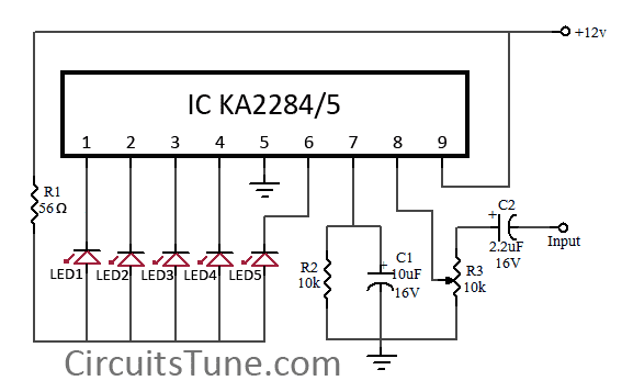
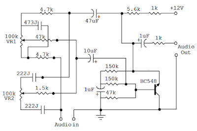


Circuit Schematic

The crystal oscillator is based on a very fast HF transistor, Tl (BFR91), which performs the amplitude modulation. Apart from this there is little to be said about the oscillator except, perhaps, that it is essential to use the correct values for the components surrounding Tl. This is, of course, simply common sense in this sort of HF circuit.

The harmonics generator is formed by two Schottky diodes, Dl and D2. These diodes must switch very quickly in time with the 27 MHz signal so they provide strong harmonics up into the gigahertz range. The modulation depth can be set with Pl, while the oscillators d.c. value can be varied by means of P2. The combination of these two presets enables either positive or negative amplitude modulation to be selected.

This is essential as the harmonics produced vary in this respect. We will discuss the calibration of Pl and P2 later in this article. The power for the circuit can be provided by either an unstabilized 8...30 V or a stabilized 5 V. The latter could be taken from a computers power supply and in this case ICI is not needed.
The printed circuit board for the modulator is only single-sided. The largecopper surface acts as a ground plain.
Parts list
Resistors:
R1, R2 = 4k7
R3, R4 = 56ohm
P1 = 100 ohm preset
P2 = 500 ohm preset
Capacitors:
C1 = 4mf7/16 V
C2= 10p
C3 = 220p
C4 = 47p
C5 = 47n, ceramic
C6 = 100n*
C7 = 330n*
Inductors:
L1, L2 = 3.5 turns of 0.2 mm (SWG 35 or 36) CuL on a ferrite bead of about 3.5 x 3.5 mm
L3 = 1 microH
L4 = 1 turn of 0.8. . .1 mm (SWG 19...21) CuL, air wound with a diameter of 8 mm
Semiconductors:
D1, D2 = 1N6263 (Ambit/Cirkit)
D3 = lN4148
T1 = BFR91 (Ambit/Cirkit)
IC1 = 7805*
Miscellaneous:
X1 = crystal, 27 MHzd(3rd overtone) or other 3rd overtone crystal between 25 and 30 MHz

*= not needed if the circuit is powered from a stabilised 5 V supply 
Read More..

Circuit design tutorial in CircuitMaker 5

In this tutorial we are going to learn how to design and simulate a circuit schematic in CircuitMaker 5. For example we are going to design a 12V to 5V  dc-dc converter circuit diagram.  This is the circuit below that we are going to design. 

Fig-1: 12V to 5V  dc-dc converter circuit diagram


Let’s start design the circuit in circuitmaker 5.


Step-1: Open a new document.
Go to “File>New” as shown below or simply press “CTRL+N” 


This will opened a new workspace named as "UNTITLED.CKT(1)".As shown below...


Step-2: Device Selection.

Click on  “Parts”-(Use to display and select device) tool icon form tool bar. See below…

Or, simply hit on “x” from keyboard.This will bring up  “Device Selection” window.From this window select a 12V DC voltage soure by “Sources>Linear>V source” and change the voltage 10V to 12V as shown below.


After that click on “Select” or press “Enter”.

Now place the symbol where you like by left click on mouse .I placed here..


In the same way add a 78L05 regulator IC symbol. See below… 


And place it in workspace.


As same as add a Diode(shortcut key “d”), Capacitor(shortcut key “c”),and Ground(shortcut key “0”) symbol one after one in the same way and place in workspace(see below). To rotate  any device click on device and press “ALT+R”once or two times or as needed.


To see the circuit in zoom view press F2 . Then you see “Circuit Scale” window, enter a value between 10 to 2000 % that you want to scale (I’m entered 150%). And press “ENTER”.

Now the circuit symbol will larger, now we can design the circuit in circuitmaker 5 easily.


Back to adding schematic symbol.

Now add two “Terminal” (see below...)


Do that two times and then rotate as shown below.


Step-3: Connect the circuit.

Select the “Wire tool” (see below…) 


To connect two pins of two device click to pin(1) and drag until to pin(2). See below…

 
Connect all the pins that are necessary (see Fig:1).

After connect the circuit its looks something like this…


Step-4: Simulate the circuit using circuitmaker simulator.


Don’t worry, this is a simple task. But simulation is necessary for a circuit. To determine that it have any error or it giving us the expected output or not.

Before simulate the circuit we have to confirm that the simulation mode is Analog. To select Analog mode click once on “Digital/Analog” button from toolbar. And then the icon will change. See below...


Now click on “Run/Stop” button from toolbar. See below...


If a confirmation massages box come then select “Yes”.

Then you will see the simulation window. See below...

Showing input value of 12V to 5V  dc-dc converter circuit diagram
Showing output value of 12V to 5V  dc-dc converter circuit diagram
 
Note: If you want to change any parts/device/source value in the circuit, double click on the parts/device/source and enter your value.
Read More..

5 LED VU meter circuit diagram using KA2284

This is a simple circuit diagram of 5-LED audio VU meter using IC KA2284/KA2285. The KA2284, KA2285 are monolithic integrated circuit. It is a logarithmic display driver IC. And it is Bar type display driver using 5-Dot LED. The KA2284/KA2285 has a wide range supply voltage capacity of 3.5V-16V, but we recommend to use about a 12VDC power supply.

Circuit Diagram:


KA2284-led
Fig: 5-LED Dot/Bar (VU meter) circuit diagram

Usability of this circuit:

  • AC signal Meter or DC Level meter.
  • Audio VU(Volume Unit) meter in amplifier or such kind of device.
Here IC AN6884 is also can be used instead of KA2284,KA2285. These all are almost same.
Further reading: DOT vs BAR
Read More..

Bass and Treble Controller Audio Equalizer Circuit

An audio equalizer circuit is used to adjust the frequency response of an audio signal. This is a simple equalizer circuit  for controlling the bass and treble (tone) of an audio amplifier. For use this equalizer circuit in amplifier, equalizers output should be given in the input of amplifier. So that the main input  audio signal’s bass and treble could be controllable before the amplify section.

Circuit Diagram of Bass & Treble Controller- Audio Equalizer:


Audio
Fig: Audio equalizer circuit for Bass, Treble control
As shown here the bass and treble controller circuit  has two variable resistor(VR1 & VR2) to control  the bass and treble. VR1 for Bass Control and VR2 for Treble Control.
This Bass and Treble controller circuit needed a  12Volt power supply. I would have designed it  in that way because 12V is used in most of the audio amplifier circuit.  and since equalizer circuit is used with audio amplifier, so therenoextrapowersupplywillrequiredforthisEqualizer.  This audio equalizer circuit is very easy to build and has a very good quality.
Read More..

Wednesday, November 12, 2014

VHF RF Single Chip Preamplifier circuit with explanation

Here is a high performance RF amplifier for the entire VHF broadcast and PMR band (100-175 MHz) which can be successfully built without any special test equipment. The grounded-gate configuration is inherently stable without any neutralization if appropriate PCB layout techniques are employed. The performance of the amplifier is quite good.
The noise figure is below 2 dB and the gain is over 13 dB. The low noise figure and good gain will help car radios or home stereo receivers pick up the lower-power local or campus radio stations, or distant amateur VHF stations in the 2-metres band. Due to the so-called threshold effect, FM receivers loose signals abruptly so if your favourite station fades in and out as you drive, this amplifier can cause a dramatic improvement.
The MAX2633 is a low-voltage, low-noise amplifier for use from VHF to SHF frequencies. Operating from a single +2.7 V to +5.5V supply, it has a virtually flat gain response to 900 MHz. Its low noise figure and low supply current makes it ideal for RF receive, buffer and transmit applications. The MAX2633 is biased internally and has a user-selectable supply current, which can be adjusted by adding a single external resistor (here, R1). This circuit draws only 3 mA current.

VHF RF preamplifier circuit diagram

Besides a single bias resistor, the only external components needed for the MAX2630 family of RF amplifiers are input and output blocking capacitors, C1 and C3, and a VCC bypass capacitor, C2. The coupling capacitors must be large enough to contribute negligible reactance in a 50-Ω system at the lowest operating frequency. Use the following equation to calculate their minimum value:
Cc = 53000/ flow [pF]
Read More..

UC3844 Design Circuit Multi Output Power Supply

This article below shows Multi Output Power Supply Circuit Design using UC3844. It is designed for power over ethernet applications (POE) or receiver end. The UC3844 acts as the isolated flyback converter which its current mode controller set to operate at 200kHz.

Together with LX1752 which generates the step down dual outputs, this power supply circuitry may have features such 36V to 57V input range, 13W input, adjustable output voltages using external resistors, isolated flyback output, step down switching regulator and power device interface.

See completely about Multi Output Power Supply Circuit Design using UC3844 here (source: microsemi.com)

Read More..

7555 or TS555CN based Courtesy Light circuit


15 seconds delayed switch-off, A good idea for bedroom lamps
This circuit is intended to let the user turn off a lamp by means of a switch placed far from bed, allowing him enough time to lie down before the lamp really switches off. Obviously, users will be able to find different applications for this circuit in order to suit their needs.

Parts :
R1 = 470R 1/2W
R2 = 100K
R3 = 1M5
R4 = 1K
C1 = 330nF-400V
C2 = 100µF-25V
C3 = 10nF-63V
C4 = 10µF-25V
C5 = 10nF-63V
D1 = 1N4007
D2 = 1N4007
D3 = BZX79C10
D4 = TIC206M
Q1 = BC557
IC1 = 7555 or TS555CN CMos Timer IC
SW1 = SPST Mains suited Switch

Circuit operation:
Due to the low current drawing, the circuit can be supplied from 230Vac mains without a transformer. Supply voltage is reduced to 10Vdc by means of C1 reactance, a two diode rectifier cell D1 & D2 and Zener diode D3. IC1 is a CMos 555 timer wired as a monostable, providing 15 seconds on-time set by R3 & C4. When SW1 is closed, IC1 output (pin 3) is permanently on, driving Triac D4 which in turn feeds the lamp. Opening SW1 operates the monostable and, after 15 seconds, pin 3 of IC1 goes low switching off the lamp.

Read More..

Typical Throttle Position Sensor Circuit Diagram

Here is a typical schematic diagram of the car Throttle Position Sensor Circuit. The Throttle Position Sensor (TPS) is designed to indicates the position of the throttle valve. Usually the Throttle Position Sensor is mounted on the throttle body and converts the throttle valve angle into an electrical signals. Inside the TPS is a resistor and a wiper arm. The arm is always contacting the resistor.
 Throttle
How the Throttle Position Sensor works?
A wiper arm inside the sensor is mechanically connected to a moving part, such as valve or vane. As the part moves, the wiper arm also moves. The wiper arm is also in contact with a resistor. As the wiper arm moves on the resistor, the signal voltage output changes which indicates position.
Read More..

Tuesday, November 11, 2014

PIC 12F629 – 12F675 based Astable Timer circuit with explanation


This software functions as a long period astable mutivibrator. The mark and space period can be set from 1 second up to a maximum 65535 seconds (18h12m15s). Using the internal 4Mhz RC oscillator delays with an accuracy of 99% or better can be achieved The code also implements an edge triggered reset and an active low hold function. The reset edge can be configured for rising or falling edge. The hold function is active low and stretches the timed period for as long as the hold input is held low. In addition to this up to 128 mark/space time pairs can be used which are executed sequentially allowing complex pulse trains to be generated. 
Read More..

Battery Saver Circuit

A small electronic switch that connects a battery to the equipment for a certain amount of time when a push-button is momentarily pressed. And we have also taken the ambient light level into account; when it is dark you won’t be able to read the display so it is only logical to turn the switch off, even if the time delay hasn’t passed yet. The circuit is quite straightforward. For the actual switch we’re using a well-known MOSFET, the BS170. A MOSFET (T2 in the circuit) used in this configuration doesn’t need a current to make it conduct (just a voltage), which makes the circuit very efficient. When the battery is connected to the battery saver circuit for the first time, capacitor C2 provides the gate of the MOSFET with a positive voltage, which causes T2 to conduct and hence connect the load (on the 9 V output) to the battery (BT1). C2 is slowly charged up via R3 (i.e. the voltage across C2 increases).

Circuit diagram:
battery-saver-circuit-diagramw
Battery Saver Circuit Diagram
This causes the voltage at the gate to drop and eventually it becomes so low that T2 can no longer conduct, removing the supply voltage to the load. In this state the battery saver circuit draws a very small current of about 1 µA. If you now press S1, C2 will discharge and the circuit returns to its initial state, with a new turn-off delay. Resistor R5 is used to limit the discharge current through the switch to an acceptable level. You only need to hold down the switch for a few hundredths of a second to fully discharge C2. In our prototype, connected between a 9 V battery and a load that drew about 5 mA, the output voltage started to drop after about 26 minutes. After 30 minutes the voltage had dropped to 2.4 V. You should use a good quality capacitor for C2 (one that has a very low leakage current), otherwise you could have to wait a very long time before the switch turns off! 

The ambient light level is detected using an LDR (R1). An LDR is a type of light sensor that reduces in resistance when the light level increases. We recommend that you use an FW150, obtainable from e.g. Conrad as part number 183547-89. When there is too little light its resistance increases and potential divider R1/R2 causes transistor T1 to conduct. T1 then charges up C2 very quickly through R4, which limits the current to a safe level. This stops T2 from conducting and the load is turned off. The choice of value for R2 determines how dark it has to be before T1 starts to conduct. The battery saver circuit can be added to devices that use 6 or 9 volt batteries and which don’t draw more than 100 mA. The circuit can be built on a piece of experimenter’s board and should be made as compact as possible so that it can be built into the battery powered device.
Copyright : Elektor Electronics
Read More..

Sunday, November 9, 2014

Model Railway Short Circuit Beeper

Short circuits in the tracks, points or wiring are almost inevitable when building or operating a model railway. Although transformers for model systems must be protected against short circuits by built-in bimetallic switches, the response time of such switches is so long that is not possible to immediately localise a short that occurs while the trains are running, for example. Furthermore, bimetallic protection switches do not always work properly when the voltage applied to the track circuit is relatively low. The rapid-acting acoustic short-circuit detector described here eliminates these problems. However, it requires its own power source, which is implemented here in the form of a GoldCap storage capacitor with a capacity of 0.1 to 1 F. A commonly available reed switch (filled with an inert gas) is used for the current sensor, but in this case it is actuated by a solenoid instead of a permanent magnet.

An adequate coil is provided by several turns of 0.8–1 mm enamelled copper wire wound around a drill bit or yarn spool and then slipped over the glass tube of the reed switch. This technique generates only a negligible voltage drop. The actuation sensitivity of the switch (expressed in ampère-turns or A-t)) determines the number of turns required for the coil. For instance, if you select a type rated at 20–40 A-t and assume a maximum allowable operating current of 6 A, seven turns (40 ÷ 6 = 6.67) will be sufficient. As a rule, the optimum number of windings must be determined empirically, due to a lack of specification data. As you can see from the circuit diagram, the short-circuit detector is equally suitable for AC and DC railways. With Märklin transformers (HO and I), the track and lighting circuits can be sensed together, since both circuits are powered from a single secondary winding.


Coil L1 is located in the common ground lead (‘O’ terminal), so the piezoelectric buzzer will sound if a short circuit is present in either of the two circuits. The (positive) trigger voltage is taken from the lighting circuit (L) via D1 and series resistor R1. Even though the current flowing through winding L1 is an AC or pulsating DC current, which causes the contact reeds to vibrate in synchronisation with the mains frequency, the buzzer will be activated because a brief positive pulse is all that is required to trigger thyristor Th1. The thyristor takes its anode voltage from the GoldCap storage capacitor (C2), which is charged via C2 and R2.

The alarm can be manually switched off using switch S1, since although the thyristor will return to the blocking state after C2 has been discharged if a short circuit is present the lighting circuit, this will not happen if there is a short circuit in the track circuit. C1 eliminates any noise pulses that may be generated. As a continuous tone does not attract as much attention as an intermittent beep, an intermittent piezoelectric generator is preferable. As almost no current flows during the intervals between beeps and the hold current through the thyristor must be kept above 3 mA, a resistor with a value of 1.5–1.8 kΩ is connected in parallel with the buzzer. This may also be necessary with certain types of continuous-tone buzzers if the operating current is less than 3 mA. The Zener diode must limit the operating voltage to 5.1 V, since the rated voltage of the GoldCap capacitor is 5.5 V.

Author: R. Edlinger - Copyright: Elektor Electronics
Read More..

Friday, November 7, 2014

230 V AC To 400 V DC Power Supply Circuit Diagram


Description               A lot of students are who dont know how to convert 230 volt AC to 400 DC. So today I am published   230 V AC to 400 V DC circuit diagram on my blog. Working principle of this circuit diagram is very simple. You already knew the working principle of a bridge rectifier. This circuit is same as bridge rectifier and the working principle is also same. The fuse is used to protect the circuit, if the current is greater than 1 A.
Parts List
Component No:Value
F11 A
B1IN4007 
C1470MF/450V 
V1230 V AC 


Read More..