Thursday, November 13, 2014
Bass and Treble Controller Audio Equalizer Circuit
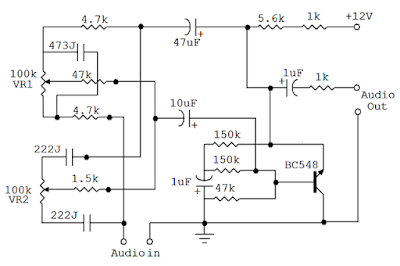
An audio equalizer circuit is used to adjust the frequency response of an audio signal. This is a simple equalizer circuit for controlling the bass and treble (tone) of an audio amplifier. For use this equalizer circuit in amplifier, equalizers output should be given in the input of amplifier. So that the main input audio signal’s bass and treble could be controllable before the amplify section.
Circuit Diagram of Bass & Treble Controller- Audio Equalizer:
 |
| Fig: Audio equalizer circuit for Bass, Treble control |
As shown here the bass and treble controller circuit has two variable resistor(VR1 & VR2) to control the bass and treble. VR1 for Bass Control and VR2 for Treble Control.
This Bass and Treble controller circuit needed a 12Volt power supply. I would have designed it in that way because 12V is used in most of the audio amplifier circuit. and since equalizer circuit is used with audio amplifier, so therenoextrapowersupplywillrequiredforthisEqualizer. This audio equalizer circuit is very easy to build and has a very good quality.
Subscribe to:
Post Comments (Atom)
Hello,
ReplyDeleteI think BC 548 is npn, and so the collector to ground?
regards