Showing posts with label and. Show all posts
Showing posts with label and. Show all posts
Thursday, November 13, 2014
Yamaha DT250 350 Mikuni Carburetor Schematic and Diagram
 The following Mikuni Carburetor Schematic and Diagram apply for Yamaha DT250 and DT350 series. The carburetor consists of following parts: pilot jet, float needle seat assembly, washer, o-ring, needle jet set bolt, needle jet washer, main jet, gasket, cover bolt, float, float lever arm, float pivot pin, float bowl gasket, float bowl, plate, float bowl screw, needle jet, throttle slide, clip, spring seat, throttle slide return spring, clip, carburetor cap, cable adjuster, etc.
 Find detail diagram and schematics of Yamaha DT250|350 Mikuni Carburetor here – http://www.slimduck.com/dt250_dt360_carburetor.gif – source: slimduck.com.

Bass and Treble Controller Audio Equalizer Circuit
An audio equalizer circuit is used to adjust the frequency response of an audio signal. This is a simple equalizer circuit for controlling the bass and treble (tone) of an audio amplifier. For use this equalizer circuit in amplifier, equalizers output should be given in the input of amplifier. So that the main input audio signal’s bass and treble could be controllable before the amplify section.
Circuit Diagram of Bass & Treble Controller- Audio Equalizer:
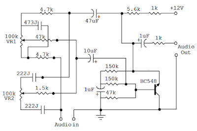 |
| Fig: Audio equalizer circuit for Bass, Treble control |
As shown here the bass and treble controller circuit has two variable resistor(VR1 & VR2) to control the bass and treble. VR1 for Bass Control and VR2 for Treble Control.
This Bass and Treble controller circuit needed a 12Volt power supply. I would have designed it in that way because 12V is used in most of the audio amplifier circuit. and since equalizer circuit is used with audio amplifier, so therenoextrapowersupplywillrequiredforthisEqualizer. This audio equalizer circuit is very easy to build and has a very good quality.
Wednesday, September 17, 2014
BC549C and BC547B Microphone amplifier
BC549C and BC547B microphone general description:
 The preamplifier amplifies the output signal of a microphone, so that it can be. The further amplified by a power amplifier The circuit supplies the output to a signal line. With two transistors, it is not difficult to build such a circuit. The amplifier produces little noise. In the shown embodiment, the circuit is suitable for microphones 500 and 600 Ω. 200 Ω R1 microphones should be reduces to 220 Ω and C1 should be increased to 4.7 uF. The gain is set by R2. If the average declared value of 22 K? Can be used. The maximum gain is about 200 times.
BC549C and BC547B microphone circuit:

BC549C and BC547B microphone part list:
R1 = 470 Ω
R 2 = 22 K?
R3 = 12 K?
R4 = 47 k
R5 = 820 Ω
R6 = 100 Ω
R7 = 1 k
R8 = 100 k
C1, C4 = 2.2 V μF/16
C2 = 47 V μF/16
C3 = 470 nF
T1 = BC 549C
T2 = BC 547B
R 2 = 22 K?
R3 = 12 K?
R4 = 47 k
R5 = 820 Ω
R6 = 100 Ω
R7 = 1 k
R8 = 100 k
C1, C4 = 2.2 V μF/16
C2 = 47 V μF/16
C3 = 470 nF
T1 = BC 549C
T2 = BC 547B
Tuesday, September 16, 2014
Mixed connection acoustics bi amplifier and the output fader
In the operation is still a lot of these "dinosaurs" of the mid 90s. A characteristic feature of built-in amplifiers such devices - they are designed for load 2 ohms and have a good supply of power. This is due to the fact that in the middle position fader front and surround speakers are connected in parallel. However, to use them in conjunction with acoustic component is impossible. The reason is simple - the introduction of the fader increases the output impedance of the amplifier, which leads to a change in crossover. Therefore, the only option enhancers such devices with modern acoustics - dual channel configuration, with the fader excluded from work.
In this version, you can add a subwoofer to include it in a "mixed-mono". Since the relationship between the levels regulate front speaker and subwoofer impossible, depending on the sensitivity applied to select one of the heads of connectivity options.

Option A is used in the case where the sensitivity of the front speakers 3-5 dB higher than that of the subwoofer. In this embodiment, they are connected to the amplifiers are not bridged, and the usual way, and the power supplied to them is not more than 7 w / 4 ohms. To obtain sufficient volume of the front acoustic desirable to use high-sensitivity head about 91-93 dB. Pay attention to their phasing - one of the "poluusiliteley" inverting the second - non-inverting. HPF cut formed by the capacitors C1 and C2 can be chosen arbitrarily, but the presence of capacitors is crucial - they do not miss out on the dynamics of the DC component from the output amplifiers. Front head shown conventionally broadband, but they may be coaxial or component.
Option B is used in nearly all heads of sensitivity. The presence of capacitors C1, C2 for the normal functioning is not necessarily because it is used in a bridge connection. In the absence of capacitors in the passband head subwoofer filter work in parallel. This reduces the load impedance to 2 ohms, but the amplifier is designed. Subwoofer in both cases the second-order filter (C3L1R1).
Wednesday, September 10, 2014
Sensor and Detector Liquids Wiring diagram Schematic
This is a very simple liquid detector which controls a relay, this gives you the option to be used for hundreds of applications. You can use it as a float switch to turn on the water pump alarm, rain, etc.. He uses a 4093 IC and transistor can be anyone, provided that it meets the power relay. This sensor can be used with Arduino no problem .
Sensor and Detector Liquids Circuit Diagram
Tuesday, September 9, 2014
Sub Woofer and Controller Wiring diagram Schematic
Sub woofers are popular, with home theater being of the driving forces. However, a nice sub adds considerably to normal hi-fi program material, & so if it is predictable & has nice response characteristics.
all of sub woofers use a immense speaker driver in a immense box, with tuning vents & all the difficulties (& vagaries) that conventional operation entails. By conventional, I mean that the speaker & cabinet are operated as a resonant technique, using the Thistle-Small parameters to get a box which will (if everything works as it ought to) provide excellent performance.
all of sub woofers use a immense speaker driver in a immense box, with tuning vents & all the difficulties (& vagaries) that conventional operation entails. By conventional, I mean that the speaker & cabinet are operated as a resonant technique, using the Thistle-Small parameters to get a box which will (if everything works as it ought to) provide excellent performance.

Completed Prototype
A fast word is warranted here, to let you decide if the speaker you have will actually work in a little sealed enclosure. The EAS principle will permit any driver to extend to twenty Hz or even lower. A lovely fast check is to stick the speaker in a box, and drive it to 100W or so at twenty Hz - you ought to see lots of cone movement, a few things will rattle, but you should not actually listen to a tone. A "bad" speaker will generate 60 Hz (third harmonic) - in the event you dont listen to anything, the speaker will work in an equalized sub.
If a tone is audible, or the speaker shows any signs of distress (such as the cone breaking up with appropriate terrible noises), then the driver cannot be used in this manner. Either discover a different driver, or use a vented enclosure.
Before you can build your own EAS box, you will require to pick an appropriate driver, using the above as a guide. Cone tour will be high at the lowest frequencies, so the speaker needs to be able to high power, lovely tour, & of reasonable size (there is no substitute for cone area for moving air at low frequencies). I am using a 380mm (15") driver, but smaller drivers (say 300mm - 12") can be used, or even a bigger number of smaller drivers. I have also had excellent results with a single 300mm driver, which has lower sensitivity (as would expect) but is perfectly adequate for normal usage.
The check methods I used are applicable to any combination, but in general I recommend either a single giant driver or a pair of (say) 300mm units. The next hurdle is the amplifier needed to drive the speaker. This is not trivial. If the selected driver has a sensitivity of 93dB / W @ one metre, then you can safely assume that the efficiency will be less than this below resonance, by a factor of possibly 6dB or more. In case you are used to driving a sub with 100W, this means that you have increased the power to 400W - although this is an over-simplification.
If they are to operate the sub from 60Hz (my aim from the outset), they will increase the power by 12dB for each octave, so if 20W is necessary at 60Hz, then at 30Hz this has increased to 320W, & at 15Hz, you will require over 5kW.
Fortunately, the reality is a tiny different, & 400W or so will be over sufficient for a powerful process, due chiefly to the fact that the energy content in the low bass region is not normally all that great. (Although some program material may have high energy content, in general this is not the case). The EAS process augments the existing process, which is allowed to roll off naturally - contrast this with the normal case, where a crossover is used to separate the low bass from the main process, so existing speaker capability is lost.
The box I built is made from 25mm (1") MDF (Medium Density Fiberboard), & filled with fiberglass. Apart from the fact that it is very heavy (which is a lovely thing, because it desires to walk with low frequencies), the cabinet is acoustically dead, with no resonances in the low frequencies at all ( unlike my house & furniture, dammit !). The woofer is recessed in to the baffle, & sealed with weather sealing foam. When attaching the speaker, do NOT use wood screws, or any other screw in to the MDF. I used "Tee" nuts. I have no idea what they are called elsewhere in the world, but they look like this

TEE NUT
The middle is tapped, and accepts a metal thread screw, and the small spikes mean that you must drill a hole, and hammer in the Tee nut. In case you use a screw through the hole and screwed lightly in to the Tee nut, you can hold it in place as you bash away at it, and can also see that it is straight when you are done. make sure that the finish of the screw doesnt stick out the finish, or you will seldom remove it again after the hammering! I recommend that you lock the tee nut in to place with some construction adhesive (dont get any in the threaded section) so they dont fall out while you are installing the speaker.
The EAS Controller
The controller is (actually very) simple, & the schema is shown in Figure one. An input buffer ensures that the input impedance of the source does not affect the integrator performance, & allows summing of left & right channels without any crosstalk. The output provides a phase reversal switch, so that the sub can be properly phased to the remainder of the process. If the mid-bass disappears as you advance the level control, then the phase is wrong, so switch to the opposite position.
The controller is (actually very) simple, & the schema is shown in Figure one. An input buffer ensures that the input impedance of the source does not affect the integrator performance, & allows summing of left & right channels without any crosstalk. The output provides a phase reversal switch, so that the sub can be properly phased to the remainder of the process. If the mid-bass disappears as you advance the level control, then the phase is wrong, so switch to the opposite position.

Figure 1 - The Original EAS Filter / Controller
It turns out that the controller can be simplified, but there is no point. While the dual pot appeared like a lovely suggestion when I built my unit, it actually only changes the gain. Now, having experimented some more, this is an excellent thing, since it means that the level through the controller can be set to make positive that there is no distortion - there can be a immense amount of gain at low frequencies, & if the gain is high, distortion is assured!
The integrators (U1B & U2A) include shelving resistors (R6 & R9), & the capacitor / resistor networks (C1-R4, C3-R7) be positive that signals below 20Hz are attenuated. In case you dont require to go that low, then the worth of the caps (or the resistors R4 & R7) can be reduced. I used four.7uF caps, & these are non-polarized electrolytic - a high value was needed to keep the impedance low to the integrators. I originally included the dual pot (VR1) to permit the upper frequency roll off to be set - however it does no such thing (as described above). The final output level is set with VR2, which may be left out if your power amp has a level control.
The integrators (U1B & U2A) include shelving resistors (R6 & R9), & the capacitor / resistor networks (C1-R4, C3-R7) be positive that signals below 20Hz are attenuated. In case you dont require to go that low, then the worth of the caps (or the resistors R4 & R7) can be reduced. I used four.7uF caps, & these are non-polarized electrolytic - a high value was needed to keep the impedance low to the integrators. I originally included the dual pot (VR1) to permit the upper frequency roll off to be set - however it does no such thing (as described above). The final output level is set with VR2, which may be left out if your power amp has a level control.
It is OK to substitute different op amps, but there is tiny reason to do so. Any substitution tool ought to be a FET input op amp, or DC offset may be an issue. Do not be tempted to make use of a DC coupled amp. If the you are planning to make use of is DC coupled, the input ought to be isolated with a capacitor. Pick a value to give a -3dB frequency of about 10Hz, as this will have tiny effect on the low frequency response, but will help to attenuate the subsonic frequencies.
The unity gain range (using a 20k pot as shown) is from 53Hz to 159Hz. This ought to be sufficient for most systems, but if desired, the resistors (R5 & R8) can be increased in value to 22k, or you can select a bigger value pot. Using 22k resistors & the 20k pot will give a range from 36Hz to 72Hz.
The unity gain range (using a 20k pot as shown) is from 53Hz to 159Hz. This ought to be sufficient for most systems, but if desired, the resistors (R5 & R8) can be increased in value to 22k, or you can select a bigger value pot. Using 22k resistors & the 20k pot will give a range from 36Hz to 72Hz.
To permit lower frequencies, you can increase the 100k shelving resistors (R6 and R9) to 220k, and increase the high pass capacitors (four.7uF) with 10uF (or R4 & R7 may be increased - a maximum of four.7k is recommended). This will give a turnover frequency of around 8Hz, but expect to make use of much more power, as there will likely be significant sub-sonic energy that will generate huge cone excursions with no audible benefit.
The input must be a standard full range (or for a stampeded method, the whole low frequency signal). Do not use a crossover or other filter before the EAS controller. For final modification, and to integrate the method in to your listening room, I recommend the constant-Q equalizer. The final result using this is extraordinarily nice - I have flat in-room response to 20Hz!
The input must be a standard full range (or for a stampeded method, the whole low frequency signal). Do not use a crossover or other filter before the EAS controller. For final modification, and to integrate the method in to your listening room, I recommend the constant-Q equalizer. The final result using this is extraordinarily nice - I have flat in-room response to 20Hz!
For the power supply, use the in anything else will provide +/-15V at a few Milli amps. My supply is not even regulated, & the whole method is as close to noiseless as you will listen to (or not listen to). Construction is not critical - I built mine on a piece of Overboard (perforated prototype board), & managed to fit everything (including the power supply rectifier & filter) on a piece about 100 x 40 millimeters with room to spare.
The EAS method is surprisingly simple to set up with no instrumentation. Of coursework in case you have an SPL meter & oscillator you can also confirm the settings with measurements. Keep in mind that the room acoustics will play havoc with the results, so unless you require to drag the whole method outside, setting by ear might be the simplest. Even in case you did get it exactly right in an anechoic surroundings, this would alter one time it was in your listening room anyway.
It takes a small experimentation to get right, but is surprisingly simple to do. When properly set, a check track (or bass guitar) ought to be smooth from the highest bass note to the lowest, with no gross peaks or dips. Some are inevitable because of room resonances & the like, but you will discover a setting that sounds "right" with small difficulty.
The EAS method is surprisingly simple to set up with no instrumentation. Of coursework in case you have an SPL meter & oscillator you can also confirm the settings with measurements. Keep in mind that the room acoustics will play havoc with the results, so unless you require to drag the whole method outside, setting by ear might be the simplest. Even in case you did get it exactly right in an anechoic surroundings, this would alter one time it was in your listening room anyway.
It takes a small experimentation to get right, but is surprisingly simple to do. When properly set, a check track (or bass guitar) ought to be smooth from the highest bass note to the lowest, with no gross peaks or dips. Some are inevitable because of room resonances & the like, but you will discover a setting that sounds "right" with small difficulty.
Performance Of My Prototype
I measured 80dB SPL at one meter in my workshop (sub-woofer perched on a chair in more or less the middle of the space) with at 25Hz & 70W. This improved dramatically when the unit was installed in the listening room, but as I said earlier, there is usually not a lot recorded below around 35Hz. The longest pipe on the organ is usually about 16Hz, but larger pipes still may be used. It was found necessary to cease group of diapasons (able to 8Hz) in the famous Sydney Town Hall organ because when they were used, the very low frequency caused building destroy.
I measured 80dB SPL at one meter in my workshop (sub-woofer perched on a chair in more or less the middle of the space) with at 25Hz & 70W. This improved dramatically when the unit was installed in the listening room, but as I said earlier, there is usually not a lot recorded below around 35Hz. The longest pipe on the organ is usually about 16Hz, but larger pipes still may be used. It was found necessary to cease group of diapasons (able to 8Hz) in the famous Sydney Town Hall organ because when they were used, the very low frequency caused building destroy.
A couple of orchestral recordings revealed traffic (or perhaps underground railway) rumble that I was unaware of before (however this was before it was set correctly, and the bass was a tad louder than needed). One time set up properly, its presence is unobtrusive - except I now have about and a half octaves of additional bottom finish.
I finally decided on a 20Hz maximum frequency (-3dB), and this is reflected in the part values shown in Figure one. The actual roll-over frequency is 16.5Hz, after which the output is attenuated at about 12dB / octave (see Figure two). Without the roll off capacitors, the gain would be 20dB at 20Hz. Unity gain frequencies are about 4Hz and 63Hz with the 20k pot(s) centered.

Figure 2 - Frequency Response of EAS Controller
awesome Australian readers may recognize the woofer brand in the picture (Figure three) of my done unit. The compact size of the box can be seen from the fact that there is tiny spacing around the speaker itself, and most of what is there is the top and sides - I used 25mm MDF, so it makes the outside of the box a bit bigger than the inside. Outside dimensions are 470W x 450H x 410D (18 1/2"W x 17 1/2"H x 16"D), which gives a capacity of 60 liters (about two.1 ft³ - excluding the internal space occupied by the speaker. I think you would agree that this is a small box indeed for a 380mm loudspeaker that performs down to 15Hz.

Figure 3 - Photo of Completed EAS Cabinet
Overall, I would must say that I doubt that any conventional design would be as compact, or would have such clarity & solidarity. Being a sealed box, there is not of the "waffle" that ported designs often give, & the speaker is protected against excessive tour by the air pressure in the box itself (below the cutoff frequency, anyway).
The bottom finish in my technique is now staggering. It is rock solid, & absolutely thunders when called on. The 400W amp is over sufficient for the job, thinking about its to keep up with a biamped main technique able to high SPL (up to 120dB at my listening position). In fact a fast check indicates that 200W would have been (but . better to have it & not require it than require it & not have it).
The fact that the EAS design augments the existing speakers than taking over from them with a crossover goes a long way towards ensuring the power requirements do not get out of hand. As an added benefit, I have found that I get the same aural sensation at much lower SPLs - I can listen happily at 90dB, but it sounds much louder. I may even listen to the phone ring while listening now !
All in all, I feel it is unlikely that anything other than an isobaric enclosure could give the same performance for a box size even close to the EAS box,& even then would be limited to about 35Hz. Added to this is the unpredictable combined response of the main speakers and the sub, which is not an Problem with this design. With an EAS system, more power is necessary than a standard design, but for plenty of people, power is less costly than space.
Sourced by : Streampowers
Sourced by : Streampowers
Friday, September 5, 2014
Car audio and stereo how to install satellite radio systems
Satellite radio represents the newest and best technology for receiving music signals. This simple guide will enable you to install a satellite radio receiver in your car.
There are several different types of satellite radio receivers available. This guide will cover the basics of installing plug and play tuners as well as hardwired in-car tuners. Plug and play tuners are units that mount on the dashboard of the vehicle. They typically come with one or more devices to connect the tuner to the stereo, as well as a cigarette lighter adapter and a mounting bracket. In-car tuners are usually rectangular boxes that will be controlled by the head unit and powered by the car power supply.
Plug and Play Tuners
- Step 1- Install the mounting bracket. Select a location that does not obstruct the driver’s view of the console or the road. The bracket should also be placed within arm’s length of the driver’s seat. To mount the bracket to the dash, first clean off the spot with alcohol wipes. Wait for this to dry, then remove the adhesive backing from the bracket and press firmly onto the dash for at least 30 seconds. Wait at least an hour before applying any weight to the bracket. The bracket can then be reinforced with screws or bolts if needed. Once the bracket is in place, slide the radio unit in place.
- Step 2- Connect the unit to the stereo. If your stereo has an auxiliary in port, use the supplied adaptor to connect the unit directly to this port. If you plan on using a cassette adapter, connection is as simple as putting the cassette into the stereo. If you choose to use an FM modulator, set both the modulator and the head unit to the same frequency.
- Step 3- Connect the antenna. If the antenna has an adhesive backing, use the same process as mounting the bracket. If the antenna is magnetic, simply place it on the roof of the car. The optimal placement for the antenna is the highest point on the car. Run the antenna wires through one of the door seals, but make sure the cord will not be damaged by the normal operation of the door. Once the cord is inside the car, run it beneath the carpet all the way up to the satellite tuner and plug it in.
- Step 4- Connect the unit to a power source. This is usually done by way of a cigarette lighter adapter. If you plan on hardwiring the power line, use crimps and appropriate fuses to make a good connection to a 12v switched power line.
- Step 5- Activate the satellite radio. This can usually be done online or over the phone. You will need the activation code for the radio. Once the radio is activated, it will function normally.
- Step 1- Mount the tuner box. Select a location that will be out-of the way, and easy accessible for wiring purposes. This is usually either in the trunk or under one of the rear seats. Use the included hardware to bolt the box into something solid. Be wary of puncturing floor panels, and be aware of what you are drilling into. Do not place the unit beneath any carpeting.
- Step 2- Wire the power lines for the box. Before you do this, disconnect the negative terminal from the car battery. Find a 12v line, either switched or non-switched, that you are able to tap into. It is best to use either the head unit power source or the cigarette lighter power source. To split the line, clip the existing cable at the desired location and crimp the three lines back together. Fuse the line before and after the split. Run the power cable beneath the carpet back to the tuner box and plug it in.
- Step 3- Hook the tuner box to the stereo. The unit should come with two cables: an RCA patch cable and a bus controller cable. Plug both of these cables into their respective ports in the tuner box and run them up to the head unit. Plug them into the ports in the back of the head unit.
- Step 4- Mount the antenna. If the antenna has an adhesive mount, first clean the area you intend to mount it on, then remove the adhesive backing and press firmly for at least 30 seconds. In the case of a magnetic mount antenna simply place it where you want it. The best mounting location is the highest point on the car. Be sure the antenna is not obstructed by any part of the car. Run the wires into the car through a door seal, then underneath the carpet until you reach the tuner box. Plug both the ground (terra) and satellite antenna cables into the unit.
- Step 5- Activate the unit by following the instructions provided. You will need the activation or identification numbers for the unit, so write these down before you call.
Head unit controlled Satellite radio
Wednesday, September 3, 2014
Simple and Nice Passive Subwoofer filter Wiring diagram Schematic
This is a Simple and Nice Passive Sub-woofer filter Circuit Diagram. This schema not required power supply because is a simple low frequency passive filter. It could be useful if you want to drive an extra sub-woofer from your stereo system.
Simple and Nice Passive Subwoofer filter Circuit Diagram
The schema filters the frequency ranges above the 150Hz. The schematic is calculated to work with a 50 watts audio amplifier, but can be used with higher powers as well. The frequency can be adjusted with 2k2 potentiometer from 50 Hz to 160 Hz.
Sunday, August 24, 2014
Nokia Prepare 3D Display Device and Tablet Windows 8
Nokia is preparing for the possibility of some additional products for Microsoft than Windows Smartphone Phone 7. One such product is a dual-screen device that can display 3D images, while the other is a tablet Windows 8.

Both these gadgets have not confirmed its existence by Nokias device with dual screen is visible from a patent application by Nokia on April 21, then under the name "Autostereoscopic Rendering and Display Apparatus" or a display device and processing autostereoskopik.
According to those files, this device consists of a sensor arranged to detect the position and orientation of ones view of the auto-stereoscopic display.
There is also a processor that is configured to determine the surface of an object that can be seen in 3D user, and an image generator arranged to create an image received by the right eye and left a visible 3D auto-stereoscopic.
From the pictures included in the patent is expected to have a 3D image processing screens and other screens such as the 2D image processing for shadows and reflections that will change according to eye position. There was no indication the user needs to wear special glasses so that the estimated Nokia would use technology like the Nintendo 3DS or better.
While the news about Windows 8 Nokia tablet is a result of a partnership with Microsoft. This news comes from rumors that issued Eldar Murtazin saying that Nokia will launch at least one tablet of Windows 8 models by 2012 or no later than 2013.
There is also information that Nokia will continue to release a Symbian-based devices in 2012 as many as 5-7 handsets upper middle class is being focused to make the phone even though Windows Phone 7. It also said that Maemo device 6 is not going to walk again with only produce as many as 92 thousand units.
Eldar also said that Nokia set a target of the global smartphone market share of 21% in 2011, and the overall mobile phone market share target of 27%.
Read More..
Both these gadgets have not confirmed its existence by Nokias device with dual screen is visible from a patent application by Nokia on April 21, then under the name "Autostereoscopic Rendering and Display Apparatus" or a display device and processing autostereoskopik.
According to those files, this device consists of a sensor arranged to detect the position and orientation of ones view of the auto-stereoscopic display.
There is also a processor that is configured to determine the surface of an object that can be seen in 3D user, and an image generator arranged to create an image received by the right eye and left a visible 3D auto-stereoscopic.
From the pictures included in the patent is expected to have a 3D image processing screens and other screens such as the 2D image processing for shadows and reflections that will change according to eye position. There was no indication the user needs to wear special glasses so that the estimated Nokia would use technology like the Nintendo 3DS or better.
While the news about Windows 8 Nokia tablet is a result of a partnership with Microsoft. This news comes from rumors that issued Eldar Murtazin saying that Nokia will launch at least one tablet of Windows 8 models by 2012 or no later than 2013.
There is also information that Nokia will continue to release a Symbian-based devices in 2012 as many as 5-7 handsets upper middle class is being focused to make the phone even though Windows Phone 7. It also said that Maemo device 6 is not going to walk again with only produce as many as 92 thousand units.
Eldar also said that Nokia set a target of the global smartphone market share of 21% in 2011, and the overall mobile phone market share target of 27%.
Subscribe to:
Posts (Atom)