Showing posts with label bass. Show all posts
Showing posts with label bass. Show all posts
Monday, January 26, 2015
Stereo Preamplifier With Bass Boost
This preamplifier was designed to cope with CD players, tuners, tape recorders etc., providing an ac voltage gain of 4, in order to drive less sensitive power amplifiers. As modern Hi-Fi home equipment is frequently fitted with small loudspeaker cabinets, the bass frequency range is rather sacrificed. This circuit features also a bass-boost, in order to overcome this problem. You can use a variable resistor to set the bass-boost from 0 to a maximum of +16dB @ 30Hz. If a fixed, maximum boost value is needed, the variable resistor can be omitted and substituted by a switch.
Stereo Preamplifier With Bass Boost Circuit diagram:
P1 = 10K
P2 = 100K
R1 = 100K
R2 = 100K
R3 = 15K
R4 = 10K
R5 = 22K
R6 = 15K
R7 = 1K
R8 = 470R
C1 = 2.2uF-25v
C2 = 2.2uF-25v
C3 = 470uF-35v
C4 = 1uF-35V
C5 = 2.2uF-25v
C6 = 47nF-63v
C7 = 22uF-25v
IC1 = TL072, Opamp
SW1 = DPST Switch
Notes:
- Schematic shows left channel only, but R1, R2, R3 and C1, C2, C3 are common to both channels.
- For stereo operation P1, P2 (or SW1), R4, R5, R6, R7, R8 and C4, C5, C6, C7 must be doubled.
- Numbers in parentheses show IC1 right channel pin connections.
- A log type for P2 ensures a more linear regulation of bass-boost.
- Needing a simple boost-in boost-out operation, P2 must be omitted and SW1 added as shown in the diagram.
- For stereo operation SW1 must be a DPST type.
- Please note that, using SW1, the boost is on when the switch is open, and off when the switch is closed.

Monday, November 17, 2014
10W Audio Amplifier with Bass boost
This Audio Amplifier design is based on the audio amplifier 18 watts, and was developed primarily to meet the requests of correspondents unable to locate the chip TLE2141C. It uses the NE5532 Dual IC wide, but obviously, its power output will be written in the 9.5 - 11.5W range, as the supply rails can not exceed ± 18V.
As amplifiers of this type are often used to drive small loudspeaker cabinets, the bass frequency range is rather sacrificed. Therefore, a Bass Boost control was inserted in the amplifier feedback loop, in order to overcome this problem, without loss of quality. The low elevation curve can reach a maximum of 16.4 dB @ 50Hz. In any case, even when the bass control is turned fully counterclockwise, the amplifiers frequency response curve shows a gentle rise: 0.8 dB at 400 Hz, 4.7 dB at 100 Hz and 6 dB at 50 Hz (referred to 1 kHz).
As amplifiers of this type are often used to drive small loudspeaker cabinets, the bass frequency range is rather sacrificed. Therefore, a Bass Boost control was inserted in the amplifier feedback loop, in order to overcome this problem, without loss of quality. The low elevation curve can reach a maximum of 16.4 dB @ 50Hz. In any case, even when the bass control is turned fully counterclockwise, the amplifiers frequency response curve shows a gentle rise: 0.8 dB at 400 Hz, 4.7 dB at 100 Hz and 6 dB at 50 Hz (referred to 1 kHz).
Thursday, November 13, 2014
Bass and Treble Controller Audio Equalizer Circuit
An audio equalizer circuit is used to adjust the frequency response of an audio signal. This is a simple equalizer circuit for controlling the bass and treble (tone) of an audio amplifier. For use this equalizer circuit in amplifier, equalizers output should be given in the input of amplifier. So that the main input audio signal’s bass and treble could be controllable before the amplify section.
Circuit Diagram of Bass & Treble Controller- Audio Equalizer:
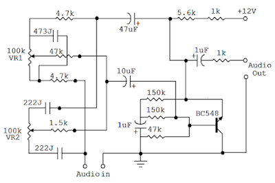 |
| Fig: Audio equalizer circuit for Bass, Treble control |
As shown here the bass and treble controller circuit has two variable resistor(VR1 & VR2) to control the bass and treble. VR1 for Bass Control and VR2 for Treble Control.
This Bass and Treble controller circuit needed a 12Volt power supply. I would have designed it in that way because 12V is used in most of the audio amplifier circuit. and since equalizer circuit is used with audio amplifier, so therenoextrapowersupplywillrequiredforthisEqualizer. This audio equalizer circuit is very easy to build and has a very good quality.
Monday, August 18, 2014
10W audio power amplifier with bass boost
 As the amplifier circuit also uses a number of frequencies to drive the loudspeaker, the bass frequencies will be reduced. Therefore need to be plugged the bass-boost control at fedback loop amplifier, this is done to overcome the decline in quality.
Sunday, August 17, 2014
Simple Bass Treble Tone Control
The LM1036 is a DC controlled tone (bass/treble), volume and balance schema for stereo applications in car radio, TV and audio systems. An additional control input allows loudness compensation to be simply effected. Four control inputs provide control of the bass, treble, balance and volume functions through application of DC voltages from a remote control system or, alternatively, from four potentiometers which may be biased from a zener regulated supply provided on the schema.
Circuit diagram :
Bass Treble Tone Control Circuit Diagram
Features:
- Wide supply voltage range, 9V to 16V
- Large volume control range, 75 dB typical
- Tone control, ±15 dB typical
- Channel separation, 75 dB typical
- Low distortion, 0.06% typical for an input level of 0.3 Vrms
- High signal to noise, 80 dB typical for an input level of 0.3 Vrms
- Few external components required
Vcc can be anything between 9V to 16V and the output capacitors are 10uF/25V electrolytic
streampowers
Subscribe to:
Posts (Atom)