Showing posts with label 8. Show all posts
Showing posts with label 8. Show all posts
Friday, October 17, 2014
13 8 Volt 10 Amp Power Supply
Sometimes amateurs like to home-brew their power supplies instead of purchasing one off the shelf at any of the major ham radio retail dealers. The advantage to rolling your own power supply is that it teaches us how they work and makes it easier to troubleshoot and repair other power supply units in the shack. It should be noted that there is no real cost advantage to building your own power supply unless you can get a large power transformer and heat sink for a super low price. Of course rolling our own gives us the ability to customize the circuit and make it even more reliable than commercial units. The circuit in Figure 1 will give us 10 amps (12 amps surge) with performance that equals or exceeds any commercial unit. The circuit even has a current limiting feature which is a more reliable system than most commercial units have. Just like other commercial units, this circuit uses the LM723 IC which gives us excellent voltage regulation. The circuit uses 3 pass transistors which must be heat sinked. Resistor R9 allows the fine tuning of the voltage to exactly 13.8 volts and the resistor network formed by resistors R4 through R7 controls the current limiting. The LM723 limits the current when the voltage drop across R5 approaches .7 volts. To reduce costs, most commercial units rely on the HFE of the pass transistors to determine the current limiting. The fault in that system is that the HFE of the pass transistors actually increases when the transistors heat up and risks a thermal runaway condition causing a possible failure of the pass transistors. Because this circuit samples the collector current of the pass transistors, thermal runaway is not a problem in this circuit making it a much more reliable power supply. The only adjustment required is setting R9 to the desired output voltage of anywhere between 10 and 14 volts. You may use a front panel mounted 1K potentiometer for this purpose if desired. Resistor R1 only enhances temperature stability and can be eliminated if desired by connecting pins 5 and 6 of IC-1 together. Although it really isn’t needed due to the type of current limiting circuit used, over voltage protection can be added to the circuit by connecting the circuit of Figure 2 to Vout. The only way over voltage could occur is if transistors Q2 or Q3 were to fail with a collector to emitter short. Although collector to emitter shorts do happen, it is more much more likely that the transistors will open up when they fail.


I actually tested this and purposely destroyed several 2N3055’s by shorting the emitters to ground. In all cases the transistors opened up and no collector to emitter short occurred in any transistor. In any event, the optional circuit in Figure 2 will give you that extra peace of mind when a very expensive radio is used with the power supply. The circuit in Figure 2 senses when the voltage exceeds 15 volts and causes the zener diode to conduct. When the zener diode conducts, the gate of the SCR is turned on and causes the SCR to short which blows the 15 amp fuse and shuts off the output voltage. A 2N6399 (Tech America) was used for the SCR in the prototype but any suitable SCR can be used. While over voltage protection is a good idea, it should not be considered a substitute for large heat sinks. I personally feel the best protection from over voltage is the use of large heat sinks and a reliable current limiting circuit. Be sure to use large heat sinks along with heat sink grease for the 2N3055 transistors. I have used this power supply in my shack for several months on all kinds of transceivers from HF, VHF to UHF with excellent results and absolutely no hum. This power supply will be a welcome addition to your shack and will greatly enhance your knowledge of power supplies.
Parts List
R1 1.5K ¼ Watt Resistor (optional, tie pins 6 & 5 of IC1 together if not used.)
R2,R3 0.1 Ohm 10 Watt Resistor (Tech America 900-1002)
R4 270 Ohm ¼ Watt Resistor
R5 680 Ohm ¼ Watt Resistor
R6,R7 0.15 Ohm 10 Watt Resistor (Tech America 900-1006)
R8 2.7K ¼ Watt Resistor
R9 1K Trimmer Potentiometer (RS271-280)
R10 3.3K ¼ Watt Resistor
C1,C2,C3,C4 4700 Microfarad Electrolytic Capacitor 35 Volt (observe polarity)
C5 100 Picofarad Ceramic Disk Capacitor
C6 1000 Microfarad Electrolytic Capacitor 25 Volt (observe polarity)
IC1 LM723 (RS276-1740) Voltage Regulator IC. Socket is recommended.
Q1 TIP3055T (RS276-2020) NPN Transistor (TO-220 Heat Sink Required)
Q2,Q3 2N3055 (RS276-2041) NPN Transistor (Large TO-3 Heat Sink Required)
S1 Any SPST Toggle Switch
F1 3 Amp Fast Blow Fuse
D1-D4 Full Wave Bridge Rectifier (RS276-1185)
T1 18 Volt, 10 Amp Transformer Hammond #165S18 (Tech America 900-5825)

Sunday, August 24, 2014
Nokia Prepare 3D Display Device and Tablet Windows 8
Nokia is preparing for the possibility of some additional products for Microsoft than Windows Smartphone Phone 7. One such product is a dual-screen device that can display 3D images, while the other is a tablet Windows 8.

Both these gadgets have not confirmed its existence by Nokias device with dual screen is visible from a patent application by Nokia on April 21, then under the name "Autostereoscopic Rendering and Display Apparatus" or a display device and processing autostereoskopik.
According to those files, this device consists of a sensor arranged to detect the position and orientation of ones view of the auto-stereoscopic display.
There is also a processor that is configured to determine the surface of an object that can be seen in 3D user, and an image generator arranged to create an image received by the right eye and left a visible 3D auto-stereoscopic.
From the pictures included in the patent is expected to have a 3D image processing screens and other screens such as the 2D image processing for shadows and reflections that will change according to eye position. There was no indication the user needs to wear special glasses so that the estimated Nokia would use technology like the Nintendo 3DS or better.
While the news about Windows 8 Nokia tablet is a result of a partnership with Microsoft. This news comes from rumors that issued Eldar Murtazin saying that Nokia will launch at least one tablet of Windows 8 models by 2012 or no later than 2013.
There is also information that Nokia will continue to release a Symbian-based devices in 2012 as many as 5-7 handsets upper middle class is being focused to make the phone even though Windows Phone 7. It also said that Maemo device 6 is not going to walk again with only produce as many as 92 thousand units.
Eldar also said that Nokia set a target of the global smartphone market share of 21% in 2011, and the overall mobile phone market share target of 27%.
Read More..
Both these gadgets have not confirmed its existence by Nokias device with dual screen is visible from a patent application by Nokia on April 21, then under the name "Autostereoscopic Rendering and Display Apparatus" or a display device and processing autostereoskopik.
According to those files, this device consists of a sensor arranged to detect the position and orientation of ones view of the auto-stereoscopic display.
There is also a processor that is configured to determine the surface of an object that can be seen in 3D user, and an image generator arranged to create an image received by the right eye and left a visible 3D auto-stereoscopic.
From the pictures included in the patent is expected to have a 3D image processing screens and other screens such as the 2D image processing for shadows and reflections that will change according to eye position. There was no indication the user needs to wear special glasses so that the estimated Nokia would use technology like the Nintendo 3DS or better.
While the news about Windows 8 Nokia tablet is a result of a partnership with Microsoft. This news comes from rumors that issued Eldar Murtazin saying that Nokia will launch at least one tablet of Windows 8 models by 2012 or no later than 2013.
There is also information that Nokia will continue to release a Symbian-based devices in 2012 as many as 5-7 handsets upper middle class is being focused to make the phone even though Windows Phone 7. It also said that Maemo device 6 is not going to walk again with only produce as many as 92 thousand units.
Eldar also said that Nokia set a target of the global smartphone market share of 21% in 2011, and the overall mobile phone market share target of 27%.
Friday, August 15, 2014
Digital 8 Channel Audio Switcher Wiring diagram Schematic
This is a Digital 8 Channel Audio Switcher Circuit Diagram. This source is selected by pressing momentary-contact push button switch SI. Switch SI is connected to the trigger of a 555 oscillator/timer (Ul) configured as a monostable multivibrator, wliich generates one short output pulse for each press of SI. That pulse turns on LED1 to give a visible indication that the 555 is working correctly.
Digital 8 Channel Audio Switcher Circuit Diagram
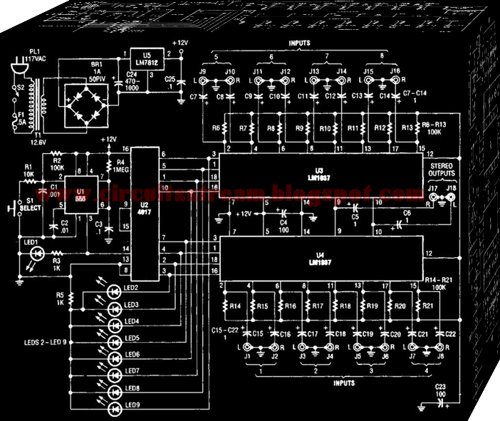
That pulse is also used to clock U2 (a 4017 CMOS divide-by- 1 -counter/divider). Both LED1 and its associated current-limiting resistor R3 arc optional and can be left out of the finished project without any affect on schema operation. The 4017 advances by one clock pulse each time SI is pressed, turning on its corresponding output. Pin 9 (corresponding to output 8) of U2 is directly connected to its own reset terminal at pin 15.
This allows the counter to count from zero to seven, and then reset to zero on the eighth count. Pin 13, the enable input ol` U2, is tied to ground to allow the counter to operate. Outputs zero through seven are connected to eight indicator LEDs and the control pins of the two LM 1037s (U3 and U4). When an output is selected, its LED lights and the corresponding control input on the LM1037 is brought high. The LM1037 has extremely high-impedance inputs and low-impedance outputs, so interconnection between various types and brands of equipment should not be a problem.
That, together with a wide-frequency response and low distortion, makes it ideal for use with good-quality, home eriter taiiunent systems. The prototype of the audio switcher has a usable frequency response of from just a few hertz to over 100 kHz. Power for the switcher is provided by a rather simple schema. Because the switcher only draws between 20 and 30 rnA, a simple schema using the popular 7812 or 78L12 (a low-power version) voltage regulator works quite well.
Saturday, August 9, 2014
10 Amp 13 8 Volt Power Supply

10 Amp 13.8 Volt Power Supply Circuit
10 Amp 13.8 Volt Power Supply Parts List :
R1 1.5K ¼ Watt Resistor (optional, tie pins 6 & 5 of IC1 together if not used.)
R2,R3 0.1 Ohm 10 Watt Resistor (Tech America 900-1002)
R4 270 Ohm ¼ Watt Resistor
R5 680 Ohm ¼ Watt Resistor
R6,R7 0.15 Ohm 10 Watt Resistor (Tech America 900-1006)
R8 2.7K ¼ Watt Resistor
R9 1K Trimmer Potentiometer (RS271-280)
R10 3.3K ¼ Watt Resistor
C1,C2,C3,C4 4700 Microfarad Electrolytic Capacitor 35 Volt (observe polarity)
C5 100 Picofarad Ceramic Disk Capacitor
C6 1000 Microfarad Electrolytic Capacitor 25 Volt (observe polarity)
IC1 LM723 (RS276-1740) Voltage Regulator IC. Socket is recommended.
Q1 TIP3055T (RS276-2020) NPN Transistor (TO-220 Heat Sink Required)
Q2,Q3 2N3055 (RS276-2041) NPN Transistor (Large TO-3 Heat Sink Required)
S1 Any SPST Toggle Switch
F1 3 Amp Fast Blow Fuse
D1-D4 Full Wave Bridge Rectifier (RS276-1185)
T1 18 Volt, 10 Amp Transformer Hammond #165S18 (Digi-Key HM538-ND)
Subscribe to:
Posts (Atom)