Showing posts with label amp. Show all posts
Showing posts with label amp. Show all posts
Wednesday, November 12, 2014
Class A EL84 6BQ5 Push Pull Tube Amp
Bruce Heran of OddWatt Audio has shared another of his great sounding OddWatt amplifier designs with the DIY community. His latest amplifier project shares a similar topology with the other OddWatt tube amplifier projects available on the DIY Audio Projects website. His latest project is similar to the first Push-Pull EL84 (6BQ5) Oddwatt project posted two years ago. Both of the tube amp projects use EL84 (6BQ5) vacuum tubes in the output stage. The first OddWatt amplifier used a ECC802S SRPP driver stage while this one uses a 5751 SRPP driver stage. The main difference between the two amps is that this one uses smaller Edcor audio output transformers making it easier and less costly to build. A photo of the finished amplifier project is shown below (click on the photo for an enlargement).
Read More..
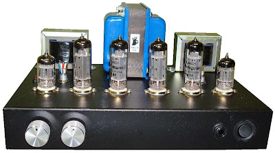
There are a number of improvements to the circuit. With the 5751 driver stage the higher gain of the new tube amp will allow for direct connection of portable MP3 players. The amplifier will produce about 5 to 7 watts of high quality sound with good performance between about 25 Hz to beyond 20kHz. The new amplifier measures very well and Bruce reports that the amp sounds very good with clean, detailed mids and highs and a great sound stage. Complete details for this project are available from the 5751 SRPP / EL84 (6BQ5) Push-Pull DIY Tube Amplifier project page.
Friday, October 17, 2014
13 8 Volt 10 Amp Power Supply
Sometimes amateurs like to home-brew their power supplies instead of purchasing one off the shelf at any of the major ham radio retail dealers. The advantage to rolling your own power supply is that it teaches us how they work and makes it easier to troubleshoot and repair other power supply units in the shack. It should be noted that there is no real cost advantage to building your own power supply unless you can get a large power transformer and heat sink for a super low price. Of course rolling our own gives us the ability to customize the circuit and make it even more reliable than commercial units. The circuit in Figure 1 will give us 10 amps (12 amps surge) with performance that equals or exceeds any commercial unit. The circuit even has a current limiting feature which is a more reliable system than most commercial units have. Just like other commercial units, this circuit uses the LM723 IC which gives us excellent voltage regulation. The circuit uses 3 pass transistors which must be heat sinked. Resistor R9 allows the fine tuning of the voltage to exactly 13.8 volts and the resistor network formed by resistors R4 through R7 controls the current limiting. The LM723 limits the current when the voltage drop across R5 approaches .7 volts. To reduce costs, most commercial units rely on the HFE of the pass transistors to determine the current limiting. The fault in that system is that the HFE of the pass transistors actually increases when the transistors heat up and risks a thermal runaway condition causing a possible failure of the pass transistors. Because this circuit samples the collector current of the pass transistors, thermal runaway is not a problem in this circuit making it a much more reliable power supply. The only adjustment required is setting R9 to the desired output voltage of anywhere between 10 and 14 volts. You may use a front panel mounted 1K potentiometer for this purpose if desired. Resistor R1 only enhances temperature stability and can be eliminated if desired by connecting pins 5 and 6 of IC-1 together. Although it really isn’t needed due to the type of current limiting circuit used, over voltage protection can be added to the circuit by connecting the circuit of Figure 2 to Vout. The only way over voltage could occur is if transistors Q2 or Q3 were to fail with a collector to emitter short. Although collector to emitter shorts do happen, it is more much more likely that the transistors will open up when they fail.


I actually tested this and purposely destroyed several 2N3055’s by shorting the emitters to ground. In all cases the transistors opened up and no collector to emitter short occurred in any transistor. In any event, the optional circuit in Figure 2 will give you that extra peace of mind when a very expensive radio is used with the power supply. The circuit in Figure 2 senses when the voltage exceeds 15 volts and causes the zener diode to conduct. When the zener diode conducts, the gate of the SCR is turned on and causes the SCR to short which blows the 15 amp fuse and shuts off the output voltage. A 2N6399 (Tech America) was used for the SCR in the prototype but any suitable SCR can be used. While over voltage protection is a good idea, it should not be considered a substitute for large heat sinks. I personally feel the best protection from over voltage is the use of large heat sinks and a reliable current limiting circuit. Be sure to use large heat sinks along with heat sink grease for the 2N3055 transistors. I have used this power supply in my shack for several months on all kinds of transceivers from HF, VHF to UHF with excellent results and absolutely no hum. This power supply will be a welcome addition to your shack and will greatly enhance your knowledge of power supplies.
Parts List
R1 1.5K ¼ Watt Resistor (optional, tie pins 6 & 5 of IC1 together if not used.)
R2,R3 0.1 Ohm 10 Watt Resistor (Tech America 900-1002)
R4 270 Ohm ¼ Watt Resistor
R5 680 Ohm ¼ Watt Resistor
R6,R7 0.15 Ohm 10 Watt Resistor (Tech America 900-1006)
R8 2.7K ¼ Watt Resistor
R9 1K Trimmer Potentiometer (RS271-280)
R10 3.3K ¼ Watt Resistor
C1,C2,C3,C4 4700 Microfarad Electrolytic Capacitor 35 Volt (observe polarity)
C5 100 Picofarad Ceramic Disk Capacitor
C6 1000 Microfarad Electrolytic Capacitor 25 Volt (observe polarity)
IC1 LM723 (RS276-1740) Voltage Regulator IC. Socket is recommended.
Q1 TIP3055T (RS276-2020) NPN Transistor (TO-220 Heat Sink Required)
Q2,Q3 2N3055 (RS276-2041) NPN Transistor (Large TO-3 Heat Sink Required)
S1 Any SPST Toggle Switch
F1 3 Amp Fast Blow Fuse
D1-D4 Full Wave Bridge Rectifier (RS276-1185)
T1 18 Volt, 10 Amp Transformer Hammond #165S18 (Tech America 900-5825)
Friday, September 19, 2014
Hammonator Organ to Guitar Amp Conversion Wiring diagram Schematic
In the world of electronics, vacuum tubes are almost obsolete. Nearly the last holdout, the cathode ray tube (CRT), is rapidly being replaced by the LCD and other new technologies. Despite this trend, the vacuum tube has seen a big revival in the field of guitar amplifiers, and to a lesser extent, hi-fi amplifiers. Vacuum tubes and related parts have become more readily available in recent years as numerous companies have tapped into this market.
The reason for the popularity of tubes in guitar amps involves the nice tones that are produced when tubes are driven to the point of distortion. For some background on this, follow some of the links on The Strat Monger. There are numerous solid state "modeling amps" that try to simulate vacuum tube amps with digital signal processing (DSP) techniques, but in the end, that method is never more than a simulation. It just aint the same as the real thing.
One can spend a large amount of money and time building a tube amp from scratch. Hammond organ ampifiers chassis are available on the surplus market for a reasonable price, they make a good starting point for a guitar amp. The difficult job of cutting chassis holes for the tubes and transformers is already done, one just needs to drill a few holes for the potentiometers and connectors. This project started with the amplifier from a Hammond M2 organ, chassis model AO14-1B.
Hammonator Organ to Guitar Amp Conversion Circuit Diagram
The output stage of this amplifier resembles a fusion between a Fender Princeton Reverb, Fender Vibroverb and ham radio transmitter. With 6V6 output tubes running at a 420V plate voltage, it puts out approximately 18 watts of audio power. The 17" reverb tank provides a deep echoey sound. The "simpler is better" philosophy was used in the design, multiple inputs with their own preamp stages were intentionally avoided to reduce hiss. The amp is plenty loud, and the sound quality is excellent. The Hammonator amp has worked well driving both 12" and 15" guitar speakers.
The Hammonator Model 1 amp is a simplified version of the Hammonator 2RVT schema. Builders can start with the Model 1 schema and easily add the Model 2RVT Vibrato/Tremolo schemary at a later date.There are a few unique features in this amp, and some slight deviations from the aforementioned simplicity goal. An optional fluorescent EM87/6HU6 "magic eye" tube (EM87 in action) is used for an output level meter, it is fun to stare at while playing. The EM87 uses a peak reading schema that was inspired by this design then modified somewhat. There is a reverb send control (Dwell) that can be used to expand the variety of reverb sounds. Most Fender amps send only a full-strength signal to the reverb spring. By turning the reverb send signal down a bit, a less "clangy" and more "spacey" reverb sound results.
The Hammonator also features a negative feedback control. With the feedback control turned all the way to the left (max negative feedback), the amp compresses the signal and the waveform peaks are reduced. With the feedback control turned all the way to the right, the sound is louder and less compressed and approaches that of the popular Fender Tweed Deluxe (5E3) amps. The feedback control could also be called "Clarity", "Gain" or "Presence".
This amp uses four octal base 6SN7 dual triode tubes for most of the low level signal amplification instead of the more common 12AX7 or 12AU7 tubes. This was done because the chassis was already set up for the octal sockets. Boutique amp enthusiasts will probably like this feature since the 6SN7 tubes are older and may have more of a vintage amp sound. Fortunately, the 6SN7 is still easy to acquire. This amp has been "tuned" for good sound, the bias settings of all of the tube stages were tweaked while a guitar was plugged in. This process was used to optimize the musical qualities of the amp. Not all vintage 6SN7 tubes are the same, quieter Sylvania tubes were used for VT1 and VT3 to reduce the hiss, nosier RCA and GE tubes were used elsewhere. You can test for noisy 6SN7 tubes by putting them in the VT1 socket, listening to the hiss level and tapping on the tube to listen for microphonics.
It is possible to change VT1, the first preamplifier and tone recovery tube, from a lower gain 6SN7 dual triode to a higher gain 6SL7 dual triode without any wiring changes. This allows the amplifier to work better with low output guitar pickups. This trick is often done with other amps by swapping 12AU7, 12AT7, 12AY7 and 12AX7 tubes, they all share the same pinout but have different gains.
The newer and more common AO-29 (M3 organ) chassis would also make a good chassis for a guitar amp conversion. The three 9 pin tube sockets could be used for 12AX7 or 12AU7 dual triode tubes and the five 7 pin tube sockets could be filled with common 6AV6 tubes (similar to a single 12AX7 triode) or 6C4 tubes (similar to a single 12AU7 triode). A similar schema layout could be used on the AO-29 chassis but the cathode bias resistor values on the 7 and 9 pin preamp triodes would need to be changed from the values used on the 6SN7 tubes. The AO-29 power transformer and output transformer are very similar to those used in the AO-14.
Connections:
Power Input - grounded 120VAC
Guitar Input - High Impedance
Reverb Send
Reverb Return
Speaker Output - 8 ohms
Controls:
On/Off (on the back)
Input Volume
Bass
Treble
Reverb Send (Dwell)
Reverb Return
Feedback (Gain)
Theory:
The AC power input schemary was modified from the original Hammond schema. The power transformer is old enough that it was designed to run on 110V-115V mains instead of the 120V mains found today. Running the stock amp on 120V produces higher filament and B+ voltages, the higher filament voltages can shorten the life of the tubes. This problem can be easily fixed by putting the 5V rectifier filament winding in series with the AC primary winding. The 5V phasing must be correct, the easy way to test this is to try both orientations and monitor the 6.3V filament winding, use the lower wiring that produces the lower voltage. When the tubes are plugged, the filament voltage should be very close to 6.3V.
A grounded plug was used, this is critical for safety. A 2 amp fuse and switch are used to provide a standard fused disconnect. The varistor on the transformer primary protects against line voltage transients, those can get multiplied on the high voltage output winding and cause damage.
The transformer high voltage winding is sent to a center tapped full wave rectifier consisting of two 1N4007 diodes. The high voltage DC is dropped through a typical chain of resistors and capacitors to produce the voltages used in the amp. The first resistor (150 ohms/2 Watt) is used to set the initial B1+ voltage that drives the power output tubes.
There is a lot of misinformation on the net about tube rectifiers vs solid state rectifiers and the effect on amp sound. This probably derives from the more efficient nature of solid state diodes and the resulting higher voltage when a direct substitution is done. Putting a resistor after the diodes drops the B+ voltage to a level that is closer to that achieved with a 5U4 rectifier. The diodes have the advantage of better efficiency due to the lack of a high power filament, the power transformer will also run cooler using diodes. The 1nF/1KV capacitors across the diodes protect against high voltage transients and eliminate RF rectification issues.
The 5H inductor choke is used to reduce hum in the preamp stages, the value is not especially critical. The 220nF capacitors in the power supply are fairly unique to this design, they improve the high frequency response of the amp. This is a trick that was borrowed from solid state schemary. If you dont have any 220nF caps, 100nF caps should do the job.
The Vbias- negative voltage is derived from a half wave rectifier and a resistive ladder. The 25K bias control can be adjusted to set the idle bias level on the power tubes. Bias levels for both 6V6 and 6L6 tubes can be generated.
The guitar input stage (VT1b) is a standard class A triode amplifier. The 1K cathode resistor was chosen to bias this most important amplifier stage into the "sweet spot". The tone controls use the Baxandall tone stack configuration. This schema has a much more distinct boost and cut operation when compared to many of the traditional Fender diagram. A guitar player friend had the amusing suggestion that the "Bass" and "Treble" labels should be changed to "Balls" and "Grit". The post-tone amplifier stage VT1a is another class A triode amplifier. Again, the 1K bias resistor was chosen for the best sound.
The reverb send amp VT2 gets its input from the tone control recovery amplifier VT1a. The 500K linear pot is used to adjust the reverb send level from half way to full. An audo taper pot was tried here, the linear pot had a better response. Both halves of VT2 are run in parallel, the 560 ohm bias resistor was chosen for the best tube drive level. VT2 runs slightly warm, with a bit of blue glow showing. A standard Fender "Twin Reverb" reverb transformer can be used to drive the reverb, I used a slightly heavier Buddy MC500 transformer.
The reverb return signal goes to two class A triode stages formed by VT3b and VT3a. The reverb return level is set with the 100K audio pot and mixed into the phase splitter stage (VT4) through a 5nF capacitor. The clean (non-reverb) signal is amplified by VT7, a 6AV6 triode wired as a floating cathode-biased stage. The 6AV6 isolates the reverb send and receive signals to prevent feedback, it also forms the heart of the vibrato/tremolo schema in the Hammonator model 2RVT design.
The balanced phase splitter schema is formed by VT4a and VT4b. This stage combined with the power tube stage is fairly close to the Fender Vibroverb schema. The two opposite-phase drive signals are sent to the control grids of the 6V6 power output tubes. An RF power amp trick is used here to reduce potential radio frequency oscillation issues, 10nF capacitors bypass the Lcd grids to ground. These caps should not be confused with the unpopular tone-deadening control grid caps that were added to Post-CBS Fender Twin Reverb amps.
A triple feedback loop is used between the output transformer and the input of the phase splitter. The low and high cut loops reduce the sub-sonic and ultra-sonic gain, eliminating any tendencies to oscillate and generate radio frequencies. While experimenting with the schema, some nearly dead power tubes were used, the tubes tended to oscillate when biased to a useful setting. These additions reduced that problem and improved the sound, RF superimposed on audio does not sound good.
A fairly heavy modem isolation transformer from a 300 baud vintage of modem was wired in series to make the low-cut inductor. When the amp is driving a speaker, there can be large resonances in the low bass part of the spectrum. A 12" speaker in an open-backed cabinet had a natural resonance around 70 Hz. Audio at the speaker resonance frequency is amplified to about twice the level as other frequencies, resulting in an exaggerated bass response and distortion. The low-cut feedback schema offsets this resonance effect.
An earlier version (obsolete) of this amp used a different anti-resonance feedback (ARF) loop that consisted of a 300 ohm resistor, a series-wired modem transformer and a 1.32uF stack of capacitors that was tuned to cancel the speaker resonance. When feeding a purely resistive load, the amplifier has a fairly flat frequency response. The low-cut/high-cut feedback loop eliminates the need to tune the amp for individual speakers.
The 6HU6 eye tube schema gets its control signal from the output transformer. The signal is rectified, low-passed and sent to the tubes control grid. The 10M bias resistor opens the tubes display farther during quiet operation. The 5K trimmer should be adjusted so that the eye tube display closes completely when the amp is played to maximum power.
Biasing the Power Tubes
If you want more than 18 Watts of power, it is possible to replace the 6V6 tubes with 6L6 tubes, simply re-adjust the bias control. The bias is set by putting a DC volt meter between the Imon1 terminal and ground. The Imon2 terminal can be checked to see if the power tubes are well matched. Both Imon1 and Imon2 should have similar voltages. The 6V6 tubes work well with a bias of around 0.17V (17 mA) and 6L6 tubes work well at around 0.35V (35mA). Tube bias setting is a trade-off between loudness and tube life. Generally, the bias should be set so that the tubes dont become too warm when there is no signal going through them.
Construction:
Here is a photo of the wiring side of the Hammonator 2RVT amp, it is essentially the Hammonator 1 schema with a few additions.The stock Hammond amp chassis that this project was built on was dirty, rusty and filled with mostly useless parts. A wire brush was used to scrape off the rust and dirt. Leave the original filament wiring from the power transformer to the 6V6 tubes intact. You will need to move one of the filament wires on some of the 6SN7 tube sockets (formerly other tube types). The power transformers high voltage leads can be left connected to the 5U4 socket, the 1N4007 rectifier diodes can be wired to the pins of the 5U4 socket. The output transformers primary wiring should be left as-is.
The ground wires that connect all of the tube sockets should be left intact. Just about everything else can be clipped off, leave all of the transformer wires as long as possible. There were two plug-boards in the center of the amp. All of the wires between the plug-boards and the tube sockets were clipped at the tube sockets and the boards were removed. The wires to the screw terminals were also clipped off. Some of the plug-board capacitors were scavanged for use elsewhere.
A new 3-wire power cord power switch were installed in the small metal wiring box that is located behind the power transformer. Two of the downward-facing holes in the wiring box were expanded to fit the power cords strain relief and the switch. A plastic "pigtail" type of fuse holder was also installed in the box. The power cables green ground wire was connected to the chassis with a solder lug.
The two tall electrolytic capacitors were removed from the chassis. The silver capacitors hole was filed out and drilled to fit the 6HU6 eye tube socket. A sheet metal filler was installed in the black capacitors hole (the photo above was taken before this was done). The volume pedal tower was disassembled and the empty space was used as a "doghouse" for most of the electrolytic capacitors. The caps were secured to the towers bakelite spacers with panduit ties. The tower allows the amp to sit upside down without resting on the tubes, this is very useful when working on the amp.
Wednesday, September 3, 2014
Simple Power Op Amp Wiring diagram Schematic
This is a best electronic schema for engineers, students and hobbyist this is a simple schema diagram. This Simple Power Op Amp Circuit Diagram from Apex Micro technology can deliver 180 V p-p @ 90 kHz into a 4- load. The PA04 can deliver 400-W RMS into an 8- load with low THD at frequencies beyond 20 kHz. Make this schema care fully and enjoy this one.
Simple Power Op Amp Circuit Diagram
Saturday, August 9, 2014
10 Amp 13 8 Volt Power Supply

10 Amp 13.8 Volt Power Supply Circuit
10 Amp 13.8 Volt Power Supply Parts List :
R1 1.5K ¼ Watt Resistor (optional, tie pins 6 & 5 of IC1 together if not used.)
R2,R3 0.1 Ohm 10 Watt Resistor (Tech America 900-1002)
R4 270 Ohm ¼ Watt Resistor
R5 680 Ohm ¼ Watt Resistor
R6,R7 0.15 Ohm 10 Watt Resistor (Tech America 900-1006)
R8 2.7K ¼ Watt Resistor
R9 1K Trimmer Potentiometer (RS271-280)
R10 3.3K ¼ Watt Resistor
C1,C2,C3,C4 4700 Microfarad Electrolytic Capacitor 35 Volt (observe polarity)
C5 100 Picofarad Ceramic Disk Capacitor
C6 1000 Microfarad Electrolytic Capacitor 25 Volt (observe polarity)
IC1 LM723 (RS276-1740) Voltage Regulator IC. Socket is recommended.
Q1 TIP3055T (RS276-2020) NPN Transistor (TO-220 Heat Sink Required)
Q2,Q3 2N3055 (RS276-2041) NPN Transistor (Large TO-3 Heat Sink Required)
S1 Any SPST Toggle Switch
F1 3 Amp Fast Blow Fuse
D1-D4 Full Wave Bridge Rectifier (RS276-1185)
T1 18 Volt, 10 Amp Transformer Hammond #165S18 (Digi-Key HM538-ND)
Subscribe to:
Posts (Atom)