Showing posts with label 5. Show all posts

Thursday, November 13, 2014

Circuit design tutorial in CircuitMaker 5

In this tutorial we are going to learn how to design and simulate a circuit schematic in CircuitMaker 5. For example we are going to design a 12V to 5V  dc-dc converter circuit diagram.  This is the circuit below that we are going to design. 

Fig-1: 12V to 5V  dc-dc converter circuit diagram


Let’s start design the circuit in circuitmaker 5.


Step-1: Open a new document.
Go to “File>New” as shown below or simply press “CTRL+N” 


This will opened a new workspace named as "UNTITLED.CKT(1)".As shown below...


Step-2: Device Selection.

Click on  “Parts”-(Use to display and select device) tool icon form tool bar. See below…

Or, simply hit on “x” from keyboard.This will bring up  “Device Selection” window.From this window select a 12V DC voltage soure by “Sources>Linear>V source” and change the voltage 10V to 12V as shown below.


After that click on “Select” or press “Enter”.

Now place the symbol where you like by left click on mouse .I placed here..


In the same way add a 78L05 regulator IC symbol. See below… 


And place it in workspace.


As same as add a Diode(shortcut key “d”), Capacitor(shortcut key “c”),and Ground(shortcut key “0”) symbol one after one in the same way and place in workspace(see below). To rotate  any device click on device and press “ALT+R”once or two times or as needed.


To see the circuit in zoom view press F2 . Then you see “Circuit Scale” window, enter a value between 10 to 2000 % that you want to scale (I’m entered 150%). And press “ENTER”.

Now the circuit symbol will larger, now we can design the circuit in circuitmaker 5 easily.


Back to adding schematic symbol.

Now add two “Terminal” (see below...)


Do that two times and then rotate as shown below.


Step-3: Connect the circuit.

Select the “Wire tool” (see below…) 


To connect two pins of two device click to pin(1) and drag until to pin(2). See below…

 
Connect all the pins that are necessary (see Fig:1).

After connect the circuit its looks something like this…


Step-4: Simulate the circuit using circuitmaker simulator.


Don’t worry, this is a simple task. But simulation is necessary for a circuit. To determine that it have any error or it giving us the expected output or not.

Before simulate the circuit we have to confirm that the simulation mode is Analog. To select Analog mode click once on “Digital/Analog” button from toolbar. And then the icon will change. See below...


Now click on “Run/Stop” button from toolbar. See below...


If a confirmation massages box come then select “Yes”.

Then you will see the simulation window. See below...

Showing input value of 12V to 5V  dc-dc converter circuit diagram
Showing output value of 12V to 5V  dc-dc converter circuit diagram
 
Note: If you want to change any parts/device/source value in the circuit, double click on the parts/device/source and enter your value.
Read More..

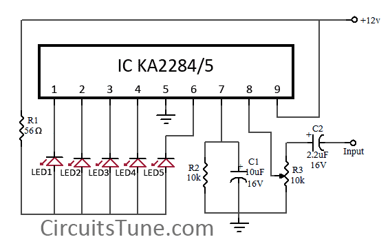
5 LED VU meter circuit diagram using KA2284

This is a simple circuit diagram of 5-LED audio VU meter using IC KA2284/KA2285. The KA2284, KA2285 are monolithic integrated circuit. It is a logarithmic display driver IC. And it is Bar type display driver using 5-Dot LED. The KA2284/KA2285 has a wide range supply voltage capacity of 3.5V-16V, but we recommend to use about a 12VDC power supply.

Circuit Diagram:


KA2284-led
Fig: 5-LED Dot/Bar (VU meter) circuit diagram

Usability of this circuit:

  • AC signal Meter or DC Level meter.
  • Audio VU(Volume Unit) meter in amplifier or such kind of device.
Here IC AN6884 is also can be used instead of KA2284,KA2285. These all are almost same.
Further reading: DOT vs BAR
Read More..

Wednesday, November 12, 2014

1 5 Volt Tracking Transmitter


The current draw for this tracker is 3.7mA, so the 1.5V button cell will last awhile. What the heck am I suppose to hear you ask? When your circuit is working you should see the LED flash quite fast. Take your FM radio and search for the low-beat ‘humbe-humbe-humbe-etc’ equal to the flash of the LED (probably around the 100Mhz). Found it? If that position is interferering with a radio station you can fine-tune it with the variable capacitor. If you like to have the tracker around the 88Mhz you can do that by spreading the windings from the home-made coil just a bit (1/2 a millimeter or so). Anyways, play with it and learn. It is a nice project. The 12-inch antenna can be anything, it is not really that critical. I used a piece of 22 gauge flexible wire. I haven’t checked the range but will do that shortly.

* For stability, use a NPO types for C2 & C4.

* Resistance tolerance for R1 should be 1 or 2%.

* Frequency range is the usual 87-109Mhz on the FM dial.

* The coil is made from 22 ga ‘hookup’ wire, like the solid Bell phone wire. Leave the insulation on.

* The LED is the ‘High Brightness’ type for maximum illumination.

source electro-tech-online .com
Read More..

Thursday, October 16, 2014

Variable 5 to 20V DC Supply Circuit Diagram

If you are looking for a low drop voltage regulator that can provide a power supply of 1A with an output voltage of between 5V and 20V DC, National Semiconductor LM2941 Low Dropout Adjustable Regulator is that you can pick to make use of. Its a typical dropout voltage of 0.5V which means that the input supply need only must be 0.5V DC over the desired output voltage. Its other features include internal short circuit current limit and reverse battery protection.

As shown in the schematic below, the regulator has five pins which consists of the ON/OFF control, Input Voltage, Output Voltage, Ground & Adjustable pins. ON/OFF is used for the purpose of switching on & off of the regulator. The capacitors C1 & E1 are to be placed as close as feasible to the regulator.

Variable 5 to 20V DC Supply Circuit Diagram

Variable


The output of the circuit can be varied by varying the worth of potentiometer VR1 from 5V DC to 20V DC. The input voltage is limited from five.5V DC to 30V DC. Resistor R1 must be greater than 1K. The worth of the VR1 that needs to be set is calculated from the formula given below:

VR1 = R1[(Vout/1.275) - 1] ohm

If R1=1K, Vout = 5V, VR1 should be set to 2.9K ohm.

If R1=1K, Vout = 20V, VR1 should be set to 14.7K ohm

Read More..

Saturday, September 6, 2014

5 To 30 Minute Timer Circuit


This is so useful schema because by using this schema you can operate some thing with the delay of 5 min to 30 min.dont use NE555 here because the value of transistors it will not work here.


Parts


IC1: 7555

B1: 9V

C1: 33uF CAP

Q1: BC109C NPN

D1: 1N4004 DIODE

C2: 100n CAP

Relay 9 volt coil with c/o contact

S1: On/Off

S2: Start

S3: Range

R6,R5,R4,R3,R2,R1: 8.2M RESISTOR

R8: 100k RESISTOR

R7: 4.7k RESISTOR

Read More..