Showing posts with label led. Show all posts

Friday, November 14, 2014

INTERFACING DOT MATRIX LED DISPLAY TO 8051

An LED dot matrix display consists of a matrix of  LED’s arranged in a rectangular configuration. The desired character or graphics can be displayed by switching ON /OFF  a desired configuration of LED’s. Common display configurations available are 7×5, 8×8, 7×15, etc. LED dot matrix can be used in simple display applications where the resolution is not a big concern.  The figure below shows the arrangement of LEDs in a typical 7×5 dot matrix display.


Any individual LED or a group of LEDs in the matrix can be activated by switching the required number of rows and columns. For example, in the above figure if  Row1 is made high and Column1 is made low, the top left LED (address R1C1) will glow. As a demonstration, lets see how we can display letter “A” using the display. The tables given below shows the logic levels at each pin  for displaying A.


In the above diagram you can see that only one LED in a row will be ON at a time but any number of  LEDs in a column can be ON at a time.  That means the microcontroller’s port pin can directly drive a row but it requires  additional circuit for driving the column lines.  The circuit diagram for interfacing dot matrix display and 8051 microcontroller is shown below.

Circuit Diagram


ULN2003A Driver IC
The purpose of ULN2003A here is to drive the column lines of the display. ULN2003A is a high voltage (50V), high current (500mA per channel) darlington transistor array. Each IC has 7 channels with individual output clamp diodes. ULN2003A  an active high device, which means a logic high must be applied to the input  to make the corresponding output high. The input pins are designated as 1B, 2B, 3B, 4B, 5B, 6B, 7B while corresponding output pins are designated as 1C, 2C, 3C, 4C, 5C, 6C, 7C.  The pin configuration and simplified internal logic of ULN2003A is shown in the figure below.


Program

ORG 00H
MOV P3,#00000000B        // initializes port 3 as output port
MOV P1,#00000000B        // initializes port 1 as output port
MAIN: MOV P3,#01111110B
      MOV P1,#11111110B
      ACALL DELAY
      MOV P3,#00010001B
      MOV P1,#11111101B
      ACALL DELAY
      MOV P3,#00010001B
      MOV P1,#11111011B
      ACALL DELAY
      MOV P3,#00010001B
      MOV P1,#11110111B
      ACALL DELAY
      MOV P3,#01111110B
      MOV P1,#11101111B
      ACALL DELAY
      SJMP MAIN         // jumps back to the main loop
DELAY: MOV R6,#255D     // 1ms delay subroutine
HERE: DJNZ R6,HERE
      RET
END
Read More..

Thursday, November 13, 2014

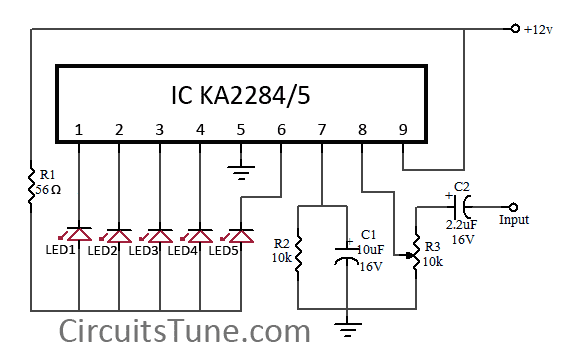
5 LED VU meter circuit diagram using KA2284

This is a simple circuit diagram of 5-LED audio VU meter using IC KA2284/KA2285. The KA2284, KA2285 are monolithic integrated circuit. It is a logarithmic display driver IC. And it is Bar type display driver using 5-Dot LED. The KA2284/KA2285 has a wide range supply voltage capacity of 3.5V-16V, but we recommend to use about a 12VDC power supply.

Circuit Diagram:


KA2284-led
Fig: 5-LED Dot/Bar (VU meter) circuit diagram

Usability of this circuit:

  • AC signal Meter or DC Level meter.
  • Audio VU(Volume Unit) meter in amplifier or such kind of device.
Here IC AN6884 is also can be used instead of KA2284,KA2285. These all are almost same.
Further reading: DOT vs BAR
Read More..

Sunday, November 9, 2014

LED Multicolour Backlights

This circuit comprises two parts: a string of 5mm high-intensity white LEDs connected in series and the circuit wired around. IC CD4060 with an inbuilt oscillator. The IC is wired such that its outputs Q4, Q5 and Q6 are chosen for colour display. On power-’on’ reset, these outputs go ‘high’ simultaneously but for different time durations. The Q4 output goes ‘high’ for about 18 seconds, Q5 about 38 seconds and Q6 about 80 seconds. These outputs are connected to forty 5mm LEDs through transistors T1, T2 and T3.

It is necessary to boost the current because LEDs are connected in parallel. To do so, transistor BD135 is used. The 1.2-kilo-ohm base resistor prevents overloading of BD135. The 100-ohm resistor acts as the current limiter. Provide heat-sink to each BD135 transistor. LEDs of three colours—blue, orange and red—are used here.

Fig. 1: Circuit for multicolour curtain backlight
To reduce the time duration for which IC outputs go high, replace 2.2-mega-ohm resistor (R4) with 1 mega-ohm. Replace 2.2-mega-ohm resistor with 3.9 mega-ohms to increase the time duration. Power supply for the IC is provided by 220V AC to 9V, 1.5A step-down transformer after rectification and filtering.

A combination of different colours results due to switching on of transistors T1 through T3 for different time durations. These colours with a white background create a beautiful display. The first group of LEDs lights up a few seconds after power to the circuit is switched ‘on.’ 
Read More..

Monday, September 15, 2014

Simple LED Torch Wiring diagram Schematic

LEDs are becoming increasingly popular in many lighting applications. White LEDs are now common in torches.

Simple LED Torch Circuit Diagram


Simple

Here’s a simple and economical LED torch that operates off two 1.5V cells. For a white LED, the forward conduction voltage and the forward current are 3.6V and 20 mA, respectively. Capacitor C1, the transistor, and the transformer form a self-oscillating DC-DC converter. The transformer boosts the input battery voltage and supplies a high voltage to the white LEDs. Diode D1 and smoothing capacitor C2 supply the high voltage to the LED chain via resistor R2.

The light intensity is affected by the input battery voltage. As the transformer is not readily available in the market, you may need to build it yourself. The transformer windings also affect the light intensity. The transformer coil is wound on a 4mm thick ferrite toroid having 13mm outer diameter and 6mm inner diameter.

Primary windings comprise 4 turns and secondary windings 55 turns of 36SWG copper-enamelled wire on toroid transformer core as shown on the right side in the figure. For the long life of 1.5V cells, keep switch S1 in ‘on’ position only when the torch is in use.


Sourced By: EFY Author :  T.A. Babu
Read More..

SP LED Flashlight Using Supercapacitor

Bored of joking with capacitors? Then its time for you to maneuver on to super-capacitors. These have huge storage capabilities. during this article you may conclude the way to build atiny low LED flashlight using supercapacitors.

The most disadvantage of capacitors is their giant voltage drop. For this project, a minimum voltage of two volts is needed to light-weight the LED. As a result, the “Joule Thief” style would be incorporated here. Using this, a AA battery is used to light-weight an LED until its fully discharged.
 during this case, a supercapacitor would be taking the place of the battery. Here an LED is employed to perform the operate of a diode. This ensures that theres sufficient voltage across the LED.

 the necessities of the project are listed below:
White LED
Super capacitor (10F, 2.7 V)
Transistor
Torus
1 k ohm resistor
Wires
Breadboard
The torus and therefore the transistor used here comes from an energy-saving lamp HS. Care ought to be taken whereas removing this from the lamp as a breakage may lead to the discharge of the mercury vapors. A lamp load along side a USB port is added to the schema. This makes it compatible with a computer or a automotive radio.


A couple of precautions got to be taken whereas constructing the schema. The USB port mustnt be supplied with excess power. The capacitor doesnt stand up to a high voltage and hence a zener diode is connected in parallel to handle the high voltage. The diode protects the capacitor when the voltage exceeds an explicit price.
Read More..

Thursday, September 11, 2014

Simple LED Photo therapy Wiring diagram Schematic

This Simple LED Photo-therapy Circuit Diagram is used for therapeutic phototherapy. Light at the correct wavelength can be effective against depression and allergies. There are a wide range of products on the market, dear, they are presented as remedies for dust allergy, fever etc.. If we look at these devices in more detail, we see that the operation is relatively simple to explain. 

Common to all devices is that they emit deep red light with a wavelength of 660 nm.Some of these devices to claim phototherapy light of 660 nm can have a positive effect on the human body and can initiate curing processes. This is so-called "phototherapy" is a treatment which is claimed to have an effect against allergic reactions in the body, as it acts against oxygen free radicals and strengthens the immune system, reducing inflammation of the mucous membrane.

This treatment has the shape of a product, but rather in the form of visible light, so there is no risk of side effects. There was a scientific study that showed that this therapy does not work in all cases, but success rates are up to 72%.

 LED Photo-therapy Circuit Diagram

LED


Simple LED Photo-therapy Circuit Diagram
Read More..

Tuesday, September 9, 2014

Make a series letters from the LED

Make a series letters from the LED , Things to consider before making the sign of the LED array,
1) Use LED nodes.
2) Paint the top of the PCB with a dark color (black).
3) Note the LED specifications. In this experiment use a 5mm diameter LED nodes
that emit red, specification voltage of 3 volts.


The assembly of LED:
1) One letter composed at most 5 columns and 7 rows.
2) One column mostly composed by 6 LEDs are arranged series.
3) Then the fifth column are connected in parallel.
4) Each column given the constraints, Rx, which amount depends on the number of LEDs in one column and depends also on the type of LED (in this experiment that used LED 5mm in diameter, clear with red light beam).
5) In a column consisting of 6 LEDs, Rx = 330 ohm, 5 LEDs, Rx = 560 Ohms, 4 LEDs, Rx = 680 Ohms
Remember, this provision applies to 5 mm LED red light beam nodes.
6) Every letter was given FCS9013 transistor amplifier.

Here is one letter LED scheme.
Make


Medium picture below is the lay out of the 2-letter nameplate. To make the sign 8 letter, copied from a second stay this letter.

Make


Example of LED on the letters A and B:

Make

Value Rx in the first and the fifth column (letter A) of 560 ohms, because it consists of 5 LEDs are arranged series. Rx in the second column, third, and fourth, amounting to 680 ohms because it consists of two LEDs.
Rx first column letter B, 330 ohms. Rx second column, third, fourth, and fifth at 680 ohms.
Read More..

Tuesday, September 2, 2014

Dimmer Brightness LED Driver Wiring diagram Schematic

This is a very simple schema of a dimmer, ie a controller LED brightness, which is powered from the USB port of a PC and a connection is very simple. The resistor R1 sets the maximum current of the LED with the maximum potentiometer, resistor R2 should have a resistance of 10x to 100x greater than R1. The table shows which components to use in accordance with the selected LED.


Dimmer-Brightness LED Driver Circuit Diagram

Dimmer-Brightness

Read More..

Thursday, August 28, 2014

Flashing LED Battery status Indicator

Signals when an on-schema battery is exhausted 5V to 12V operating voltage
A Battery-status Indicator schema can be useful, mainly to monitor portable Test-gear instruments and similar devices. LED D1 flashes to attire the users attention, signaling that the schema is running, so it will not be left on by mistake. The schema generates about two LED flashes per second, but the mean current drawing will be about 200µA. Transistors Q1 and Q2 are wired as an uncommon complementary astable multivibrator: both are off 99% of the time, saturating only when the LED illuminates, thus contributing to keep very low current consumption. 


Flashing-LED
Flashing-LED Battery-status Indicator Circuit Diagram

The schema will work with battery supply voltages in the 5 - 12V range and the LED flashing can be stopped at the desired battery voltage (comprised in the 4.8 - 9V value) by adjusting Trimmer R4. This range can be modified by changing R3 and/or R4 value slightly.

When the battery voltage approaches the exhausting value, the LED flashing frequency will fall suddenly to alert the user. Obviously, when the battery voltage has fallen below this value, the LED will remain permanently off. To keep stable the exhausting voltage value, diode D1 was added to compensate Q1 Base-Emitter junction changes in temperature. The use of a Schottky-barrier device (e.g. BAT46, 1N5819 and the like) for D1 is mandatory: the schema will not work if a common silicon diode like the 1N4148 is used in its place.

Parts :
R1,R7__________220R  1/4W Resistors
R2_____________120K  1/4W Resistor
R3_______________5K6 1/4W Resistor
R4_______________5K  1/2W Trimmer Cermet or Carbon
R5______________33K  1/4W Resistor
R6_____________680K  1/4W Resistor
R8_____________100K  1/4W Resistor
R9_____________180R  1/4W Resistor
C1,C2____________4µ7  25V Electrolytic Capacitors
D1____________BAT46  100V 150mA Schottky-barrier Diode
D2______________LED  Red 5mm.
Q1____________BC547   45V 100mA NPN Transistor
Q2____________BC557   45V 100mA PNP Transistor
B1_______________5V to 12V Battery supply
Notes :
  • Mean current drawing of the schema can be reduced further on by raising R1, R7 and R9 values.
Source : Red Circuits
Read More..

Tuesday, August 26, 2014

12 LED VU Meter Circuit

12

Here the 12 LED VU meter schema. This is a simple visual indication of the audio level signals, adaptive to various user needs. Can be adapted to different input levels, adjustable by trimmer TR1 (state) - TR2 (Gain), then rectified by diodes D1-D2 (standard negative mark-recovery periods) and driven in the main schema indication, consisting of the diodes D3 up to D13, transistors Q2-Q13 and materials that exist around them.

The visual indicator is taken from the series of diodes LED LD1-13. Each Led illuminates when the level changed during about 0,65 V. The power requirements are 100 ma full term. We can add as many steps we want LED, always assuming the power where you need the new LED.

Components List
R1 = 47Kohm
R2,3 = 1Mohm
R4,R7 = 1Kohm
R5 = 100ohm
R6 = 18Kohm
R9,11,13,15,17 = 560ohm
R19,21,23,25,27 = 560ohm
R29,31 = 560ohm
R8,10,12,14 = 4.7Kohm
R16,18,20,22 = 4.7Kohm
R24,26,28,30 = 4.7Kohm
C1 = 10uF/25V
C2 = 100nF/100V MKT
C3 = 4.7uF/25V
C4 = 4.7uF/25V
C5 = 10uF/25V
C6 = 47uF/25V
C7-8 = 100nF/100V
TR1 = 100Kohm Trimmer
TR2 = 4.7Kohm Trimmer
LD1 until LD7 = LED Green
LD8,LD9,LD10 = LED Yellow
LD11,LD12,LD13 = LED Red
D1 until D13 = 1N4148
Q1 until Q13 = BC550C - BC549B
IC1 = TL071
IC2 = 7812 [With Heatsink]
All Resistors is 1/4W 1 -5%

12 LED VU Meter Circuit source page: users.otenet.gr
Read More..

Sunday, August 24, 2014

LED Volt Meter Circuit diagram

LED Volt Meter Circuit  diagram: Here is a Simple LED Volt meter to Monitor the charge level in Lead Acid Battery or Tubular battery. The terminal voltage of the battery is indicated through a four level LED indicators. The nominal terminal voltage of a Lead Acid battery is 13.8 volts and that of a Tubular battery is 14.8 volts when fully charged. The LED voltmeter uses four Zener diodes to light the LEDs at the precise breakdown voltage of the Zener diodes. Usually the Zener diode requires 1.6 volts in excess than its prescribed value to reach the breakdown threshold level. When the battery holds 13.6 volts or more, all the Zener breakdown and all LEDs light up. When the battery is discharged below 10.6 volts, all the LEDs remain dark. So depending on the terminal voltage of the battery, LEDs light up one by one or turns off.

LED Volt Meter Circuit  diagram:

LED-Volt-Meter-schema-diagram12 LED Volt Meter Circuit Diagram
Streampowers
Read More..

Tuesday, August 19, 2014

Flip Flop Led Circuit

Flip Flop LED
Flip flop circuit is a series of free runing multivibrator given the burden of LEDs on each side of the transition changes its output signal. Flip flop circuit with LEDs is quite simple, that is prepared with 2 units and 2 units of 2N3904 transistor circuit tank circuit composed by the RC circuit. 
LED indicators signal a change that is placed on each side of the flip flop will be lit in turn by the fire and extinguished the same as the charge and discharge capacitor. Flip flop circuit is quite simple as shown in the picture below.

Flip Flop LED series

The working principle is the flip flop over when the series voltage source is given then the 10uF capacitor will be charged through R 470 and the LED will then be forwarded to triger the transistor base so that the transistor will turn ON and LEDs. this occurs alternately on each side, so that the LED light will illuminate in turn as well.
Read More..

Thursday, August 14, 2014

Build 16 Stage Bi Directional LED Sequencer

The bi-directional sequencer uses a 4 bit binary up/down counter (CD4516) and two "1 of 8 line decoders" (74HC138 or 74HCT138) to generate the popular "Night Rider" display. A Schmitt Trigger oscillator provides the clock signal for the counter and the rate can be adjusted with the 500K pot. Two additional Schmitt Trigger inverters are used as a SET/RESET latch to control the counting direction (up or down). Be sure to use the 74HC14 and not the 74HCT14, the 74HCT14 may not work due to the low TTL input trigger level. When the highest count is reached (1111) the low output at pin 7 sets the latch so that the UP/DOWN input to the counter goes low and causes the counter to begin decrementing.

 When the lowest count is reached (0000) the latch is reset (high) so that the counter will begin incrementing on the next rising clock edge. The three lowest counter bits (Q0, Q1, Q2) are connected to both decoders in parallel and the highest bit Q3 is used to select the appropriate decoder. The schema can be used to drive 12 volt/25 watt lamps with the addition of two transistors per lamp as shown below in the section below titled "Interfacing 5 volt CMOS to 12 volt loads"

Circuit diagram


schema from Link
Read More..

Wednesday, August 13, 2014

LED Circuit


Free schema diagrams 4U has given you many  LED diagram before.By using this schema you can light up a LED with 9V.This is too simple schema .So the kids also can try this schema


Read More..

Sunday, August 10, 2014

LED flasher with Transistor circuits Wiring diagram

These diagram only flash one or two LEDs. This is opposed to the light chaser diagram that can flash four or more. Of course, the simplest LED flasher is simply to use a flashing LED. The problem with that approach is you have no control over the flash rate, but it does have its use for eye catching displays for selling stuff. The diagram below give you that control, plus they can flash two LEDs alternately.
There are many possible applications for the diagram below, especially for kids, who love flashing lights. Heres some possible uses.
  • Railroad crossing signal for model railroads.
  • Safety blinkers for bicycles, etc.
  • Fun stuff for Halloween, like making those plastic Jack-O-lanterns blink (try using ultraviolet LEDs here).
  • Christmas decorations.
  • Blinkers to locate items in the dark.

Transistor LED flasher
Transistor LED flasher diagram

This schema has a lot going for it. For one thing, it only consists of two transistors, two capacitors and four resistors. That also means it consumes very little power. You can control the flash rate by changing the size of the 100k resistors (100k makes for a pretty slow rate). You can also control the duty cycle by using resistors of different values on the two sides. The 470 ohm resistors control the current through the LEDs. Normally you want to limit this to 20mA, but to conserve battery power, you may need to limit it even further. You can also connect several LEDs in series, instead of using only one for each side. With red LEDs (1 per side) and the values shown, the schema draws about 11mA. Heres what the actual schema looks like:

Transistor LED flasher schema board

On this schema, the green wires connect to the LEDs, but you can mount them on the actual schema board for some applications. The picture is about twice actual size. Here is an example of the use of this schema: 

LED flasher
Read More..