Showing posts with label battery. Show all posts

Tuesday, November 11, 2014

Battery Saver Circuit

A small electronic switch that connects a battery to the equipment for a certain amount of time when a push-button is momentarily pressed. And we have also taken the ambient light level into account; when it is dark you won’t be able to read the display so it is only logical to turn the switch off, even if the time delay hasn’t passed yet. The circuit is quite straightforward. For the actual switch we’re using a well-known MOSFET, the BS170. A MOSFET (T2 in the circuit) used in this configuration doesn’t need a current to make it conduct (just a voltage), which makes the circuit very efficient. When the battery is connected to the battery saver circuit for the first time, capacitor C2 provides the gate of the MOSFET with a positive voltage, which causes T2 to conduct and hence connect the load (on the 9 V output) to the battery (BT1). C2 is slowly charged up via R3 (i.e. the voltage across C2 increases).

Circuit diagram:
battery-saver-circuit-diagramw
Battery Saver Circuit Diagram
This causes the voltage at the gate to drop and eventually it becomes so low that T2 can no longer conduct, removing the supply voltage to the load. In this state the battery saver circuit draws a very small current of about 1 µA. If you now press S1, C2 will discharge and the circuit returns to its initial state, with a new turn-off delay. Resistor R5 is used to limit the discharge current through the switch to an acceptable level. You only need to hold down the switch for a few hundredths of a second to fully discharge C2. In our prototype, connected between a 9 V battery and a load that drew about 5 mA, the output voltage started to drop after about 26 minutes. After 30 minutes the voltage had dropped to 2.4 V. You should use a good quality capacitor for C2 (one that has a very low leakage current), otherwise you could have to wait a very long time before the switch turns off! 

The ambient light level is detected using an LDR (R1). An LDR is a type of light sensor that reduces in resistance when the light level increases. We recommend that you use an FW150, obtainable from e.g. Conrad as part number 183547-89. When there is too little light its resistance increases and potential divider R1/R2 causes transistor T1 to conduct. T1 then charges up C2 very quickly through R4, which limits the current to a safe level. This stops T2 from conducting and the load is turned off. The choice of value for R2 determines how dark it has to be before T1 starts to conduct. The battery saver circuit can be added to devices that use 6 or 9 volt batteries and which don’t draw more than 100 mA. The circuit can be built on a piece of experimenter’s board and should be made as compact as possible so that it can be built into the battery powered device.
Copyright : Elektor Electronics
Read More..

Saturday, November 8, 2014

Battery Discharger Using Discrete Components

The battery discharger published in this website may be improved by adding a Schottky diode (D3). This ensures that a NiCd cell is discharged not to 0.6–0.7 V, but to just under 1 V as recommended by the manufacturers. An additional effect is then that light-emitting diode D2 flashes when the battery connected to the terminals is flat. The circuit in the diagram is based on an astable multivibrator operating at a frequency of about 25 kHz. When transistor T2 conducts, a current flows through inductor L1, whereupon energy is stored in the resulting electromagnetic field. When T2 is cut off, the field collapses, whereupon a counter-emf is produced at a level that exceeds the forward voltage (about 1.6 V) of D2.


A current then flows through the diode so that this lights. Diode D1 prevents the current flowing through R4 and C2. This process is halted only when the battery voltage no longer provides a sufficient base potential for the transistors. In the original circuit, this happened at about 0.65 V. The addition of the forward bias of D3 (about 0.3 V), the final discharge voltage of the battery is raised to 0.9–1.0 V. Additional resistors R5 and R6 ensure that sufficient current flows through D3. When the battery is discharged to the recommended level, it must be removed from the discharger since, in contrast to the original circuit, a small current continues to flow through D3, R2-R3, and R5-R6 until the battery is totally discharged.

The flashing of D2 when the battery is nearing recommended discharge is caused by the increasing internal resistance of the battery lowering the terminal voltage to below the threshold level. If no current flows, the internal resistance is of no consequence since the terminal voltage rises to the threshold voltage by taking some energy from the battery. When the discharge is complete to the recommended level, the LED goes out. It should therefore be noted that the battery is discharged sufficiently when the LED begins to flash.
Read More..

Wednesday, September 17, 2014

Simple Nicad Battery Charger

This simple charger uses a single transistor as a constant current source. The voltage across the pair of 1N4148 diodes biases the base of the BD140 medium power transistor. The base - emitter voltage of the transistor and the forward voltage drop across the diodes are relatively stable.  The charging current is approximately 15mA or 45mA with the switch closed. This suits most 1.5V and 9V rechargeable batteries. The transformer should have a secondary rating of 12V ac at 0.5amp, the primary should be 220/240volts for Europe or 120volts ac for North America.

Simple Nicad Battery Charger Circuit diagram :


WARNING: Take care with this circuit. Use a voltmeter to observe correct polarity. Nicads can  explode if short circuited or connected with the wrong polarity.

Read More..

Monday, September 15, 2014

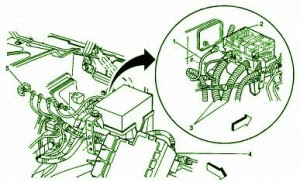
Explanation Fuse Box Chevy Truck V8 Battery 2000 Diagram

Fuse Box Chevy Truck V8 Battery 2000 Diagram - This show you about Fuse Box Chevy Truck V8 Battery 2000 Diagram.

Fuse Box Chevy Truck V8 Battery 2000 Diagram


Fuse
Fuse

Fuse Panel Layout Diagram Parts: battery cable, underhood fuse block, engine harness, remote stud.
Read More..

Saturday, September 13, 2014

Battery Powered Night Lamp


This schema is usable as a Night Lamp when a wall mains socket is not available to plug-in an ever running small neon lamp device. In order to ensure minimum battery consumption, one 1.5V cell is used and simple voltage doublers drives a pulsating ultra-bright LED: current drawing is less than 500µA. An optional Photo resistor will switch-off the schema in daylight or when room lamps illuminate, allowing further current economy. This device will run for about 3 months continuously on an ordinary AA sized cell or for around 6 months on an alkaline type cell but, adding the Photo resistor schemary, running time will be doubled or, very likely, triplicates. IC1 generates a square wave at about 4 Hz frequencies. C2 & D2 form voltage doublers, necessary to raise the battery voltage to a peak value able to drive the LED.


Parts:

R1 = 1M
R2 = 1M
R3 = 47K
R4 = LDR
C1 = 100nF-63V
C2 = 220uF-25V
D1 = Ultra Bright 10mm LED
D2 = 1N5819
B1 = 1.5V Battery or AA Cell
IC1 = 7555 CMos Timer IC


Notes:

* IC1 must be a CMos type: only these devices can safely operate at 1.5V supply or less.
* If you do not need Photo resistor operation, omit R3 & R4 and connect pin 4 of IC1 to positive supply.
* Ordinary LEDs can be used, but light intensity will be poor.
* An ordinary 1N4148 type diode can be used instead of the 1N5819 Schottky-barrier type diode, but LED intensity will be reduced due to the higher voltage drop.
* Any Schottky-barrier type diode can be used in place of the 1N5819, e.g. the BAT46, rated @ 100V 150mA.

Read More..

Saturday, August 30, 2014

iPod Battery Charger Wiring diagram Schematic


iPod Battery Charger Circuit Diagram

This is the iPod Battery Charger Part list:

P1 = 1K
R1 = 1R-0.5W
R2 = 1R-0.5W
R3 = 1R-0.5W
R4 = 1K
R5 = 560R
R6 = 10R-0.5W
R7 = 470R
C1 = 470uF-25V
C2 = 100nF-63V
C3 = 470pF
C4 = 100uF-25V
D1 = 1N5404
D2 = TVS1P6KE27A
D3 = 1N5819
D4 = 5.1V-1W Zener Diode
D5 = 5mm. Red LED
L1 = 220uH
S1 = USB A Type Socket
SW1 = On/Off Switch
IC1 = MC34063A


Using the USB port on your computer to charge your player’s batteries is not always practical. What if you do not have a computer available at the time or if you do not want to power up a computer just for charging? Or what if you are traveling? Chargers for Mobile Phones iPods and MP3 players are available but they are expensive and you need separate models for charging at home and in the car.
This charger can be used virtually anywhere. While we call the unit a charger, it really is nothing more than a 5V supply that has a USB outlet. The actual charging schema is incorporated within the iPOD or MP3 player itself, which only requires a 5V supply. As well as charging, this supply can run USB-powered accessories such as reading lights, fans and chargers, particularly for mobile phones.
The supply is housed in a small plastic case with a DC input socket at one end and a USB type "A" outlet at the other end, for connecting to Mobile Phone, an iPod or MP3 player when charging. A LED shows when power is available at the USB socket. Maximum current output is 660mA, more than adequate to run any USB-powered accessory.
Read More..

Bipolar Power supply for Battery Instruments Circuits Wiring diagram

Bipolar Power supply for Battery Instruments Circuits Diagram. To generate regulated ± 5-V supplies from a pair of dry batteries, the schema of Fig. 1 is commonly used. In order to give protection from inadvertent reverse connection of a battery, a diode in series with each battery would produce an unacceptable voltage drop. The more effective approach is to fit diodes Dl and D2 as shown in Fig. 2, in parallel with each battery. 

When the supply is switched off, there is the risk of a reverse bias being applied across the regulators, if there is significant inductance or capacitance in the load schema.Diodes across the regulators prevent damage. When the power supply is switched on, the two switches do not act in unison. There is a probability that one or the other regulators will be latched hard off by the other. To prevent this, D3 and D4 are Zener diodes so that ± 5-V rails are pulled up by the batteries until the regulators establish the correct levels.

Bipolar Power supply for Battery Instruments Circuits Diagram


Bipolar

Read More..

Thursday, August 28, 2014

Flashing LED Battery status Indicator

Signals when an on-schema battery is exhausted 5V to 12V operating voltage
A Battery-status Indicator schema can be useful, mainly to monitor portable Test-gear instruments and similar devices. LED D1 flashes to attire the users attention, signaling that the schema is running, so it will not be left on by mistake. The schema generates about two LED flashes per second, but the mean current drawing will be about 200µA. Transistors Q1 and Q2 are wired as an uncommon complementary astable multivibrator: both are off 99% of the time, saturating only when the LED illuminates, thus contributing to keep very low current consumption. 


Flashing-LED
Flashing-LED Battery-status Indicator Circuit Diagram

The schema will work with battery supply voltages in the 5 - 12V range and the LED flashing can be stopped at the desired battery voltage (comprised in the 4.8 - 9V value) by adjusting Trimmer R4. This range can be modified by changing R3 and/or R4 value slightly.

When the battery voltage approaches the exhausting value, the LED flashing frequency will fall suddenly to alert the user. Obviously, when the battery voltage has fallen below this value, the LED will remain permanently off. To keep stable the exhausting voltage value, diode D1 was added to compensate Q1 Base-Emitter junction changes in temperature. The use of a Schottky-barrier device (e.g. BAT46, 1N5819 and the like) for D1 is mandatory: the schema will not work if a common silicon diode like the 1N4148 is used in its place.

Parts :
R1,R7__________220R  1/4W Resistors
R2_____________120K  1/4W Resistor
R3_______________5K6 1/4W Resistor
R4_______________5K  1/2W Trimmer Cermet or Carbon
R5______________33K  1/4W Resistor
R6_____________680K  1/4W Resistor
R8_____________100K  1/4W Resistor
R9_____________180R  1/4W Resistor
C1,C2____________4µ7  25V Electrolytic Capacitors
D1____________BAT46  100V 150mA Schottky-barrier Diode
D2______________LED  Red 5mm.
Q1____________BC547   45V 100mA NPN Transistor
Q2____________BC557   45V 100mA PNP Transistor
B1_______________5V to 12V Battery supply
Notes :
  • Mean current drawing of the schema can be reduced further on by raising R1, R7 and R9 values.
Source : Red Circuits
Read More..

Sunday, August 24, 2014

12V Powered 12V Lead Acid Battery Charger with Indicator

Some of you might wonder why a charger is needed at all, to charge a 12 Volt battery from a 12 Volt source! Well, firstly the "12 Volt" source will typically vary anywhere from 11 Volt to 15 Volt, and then a battery needs a controlled charge current and voltage, which cannot result from connecting it directly to a voltage source. The charger described here is intended for charging small 12 Volt lead acid batteries, such as the gelled or AGM batteries of capacities between about 2 and 10 Ah, using a cars electrical system as power source, regardless of whether the car engine is running or not. I built this charger many years ago, I think I was still in school back then. On request of a reader of my web site, Im publishing it now, despite being a rather crude schema.

12V
It works, it is uncritical to build, and uses only easy-to-find parts, so it has something in its favor. The downside is mainly the low efficiency: This charger wastes about as much power as it puts into the battery. The charger consists of two stages: The first is a capacitive voltage doubler, which uses a 555 timer IC driving a pair of transistors connected as emitter followers, which in turn drive the voltage doubler proper. The doubler has power resistors built in, which limit the charging current. The second stage is a voltage regulator, using a 7815 regulator IC. Its output is applied to the battery via a diode, which prevents reverse current and also lowers the voltage a bit.

12V
The resulting charge voltage is about 14.4V, which is fine for charging a gelled or AGM battery to full charge, but is too high as a trickle charger, so dont leave this charger permanently connected to a battery. If you would like to do just that, then add a second diode in series with D3! There is a LED connected as a charge indicator. It will light when the charge current is higher than about 150mA. The maximum charge current will be roughly 400mA. There is an auxiliary output, that provides about 20V at no load (depending on input voltage), and comes down as the load increases. I included this for charging 12V, 4Ah NiCd packs, which require just a limited current but not a limited voltage for charging.

12V

Note that if the charge output is short-schemaed, the overcurrent protection of U2 will kick in, but the current is still high enough to damage the diodes, if it lasts. So, dont short the output! If instead you short the auxiliary output, the fuse should blow. I built this charger into a little homemade aluminum sheet enclosure, using dead-bug construction style. Not very tidy, but it works. Note the long leads on the power resistors. They are necessary, because with shorter leads the resistors will unsolder themselves, as they get pretty hot! The transistors and the regulator IC are bolted to the case, which serves as heat sink. The transistors dont heat up very much, but the IC does.

Source: Homo Ludens
Read More..

Saturday, August 23, 2014

Build a Heavy Duty Battery Charger Wiring diagram Schematic

How to Build a Heavy Duty Battery Charger Circuit Diagram. Operation amplifier A1 directly drives the VN64GA with the error signal to control the output voltage. Peak rectifier Dl, CI supplies error amplifier A1 and the reference zener. This extra drive voltage must exceed its source voltage by several volts for the VN64GA to pass full load current. 

The output voltage is pulsating dc which is quite satisfactory for battery charging. To convert the system to a regulated dc supply, capacitor C2 is increased and another electrolytic capacitor is added across the load. The response time is very fast, being determined by the op-amp. 

 Heavy Duty Battery Charger Circuit Diagram

Heavy


The 2N4400 current limiter schema prevents the output current from exceeding 4.5 A. However, maintaining a shorted condition for more than a second will cause the VN64GA to exceed its temperature ratings. A generous heat sink, on the order of 1°C/W, must be used.
Read More..

Wednesday, August 20, 2014

Simple Battery Charger using LM350

Simple

The schematic diagram can be used for charging the 12V lead acid batteries.

The schema is designed as a constant voltage source with a negative temperature coefficient. The transistor Q1 (BD 140) is used as the temperature sensor. The transistor Q2 is used to prevent the battery from discharging through R1 when the mains power is not available. The schema is designed based on the voltage regulator IC LM350. The output voltage of the charger can be adjusted between 13-15 V by varying the POT R6.

The LM350 will try to keep the voltage drop between its input pin and the output pin at a constant value of 1.25V. So there will be a constant current flow through the resistor R1. Q1 act here as a temperature sensor with the help of components R6/R3/R4 which more or less control the base current of Q1. As the emitter/base connection of transitor Q1, just like any other semiconductor, contains a temperature coefficient of -2mV/°C, the output voltage will also show a negative temperature coefficient. That one is only a factor of 4 larger, because of the variation of the emitter/basis of Q1 multiplied by the division factor of P1/R3/R4. This results in approximately -8mV/°C. The LED will glow whenever the mains power is available.

The transistor Q1 must be placed as close as possible to the battery.
Use a 20 to 30 V / 3A DC power supply for powering the schema.
This schema is not possible for charging GEL type batteries as it draw large amounts of current.

Here the LM350 pin layout:
 here the lm350 pin layout
Read More..

Sunday, August 17, 2014

Automatic Battery Charger Wiring diagram Schematic

Normally, chargers available in the market do not have any sort of control except for a ro-tary switch that can select different tap-pings on a rheostat, to vary the charging current. This type of control is not adequate because of the irregular fluctuations in the mains supply, rendering the control ineffective.  A simple schema intended for automatic charging of lead-acid batteries is presented here. It is flexible enough to be used for large capacity inverter batteries. Only the rating of transformer and power transistor needs to be increased.

Circuit diagram :
Automatic
Automatic Battery Charger Circuit Diagram
 
The schema has been basically designed for a car battery (about 40 Ah rating), which could be used for lighting two 40W tube lights. The schema includes Schmitt trigger relay driver,float charger,and battery voltage monitor sections.  The Schmitt trigger is incorporated to avoid relay chattering. It is designed for a window of about 1V. During charging, when the battery voltage increases be-yond 13.64V, the relay cuts off and the float charging section continues to work. When battery voltage goes below 11.66V, the relay is turned on and direct (fast) charging of the battery takes place at around 3A.  In the Schmitt trigger schema, resistors R1 and R2 are used as a simple voltage divider (divide-by-2) to provide battery voltage sample to the inverting input terminal of IC1. The non-invert-ing input terminal of IC1 is used for reference input derived from the output of IC2 (7806), using the potentiometer arrangement of resistors R3 (18 kilo-ohm) and R4 (1 kilo-ohm). 

LED1 is connected across relay to indicate fast charging mode. Diodes D3 and D6 in the common leads of IC2 and IC3 respectively provide added protecion to the regulators.  The float charging section, comprising regulator 7812, transistors T3 and T4, and few other discrete components, becomes active when the battery volt-age goes above 13.64V (such that the relay RL1 is deenergised). In the energised state of the relay, the emitter and collector of transistor T4 remain shorted, and hence the float charger is ineffective and direct charging of battery takes place. 

The reference terminal of regulator (IC3) is kept at 3.9V using LED2, LED3, and diode D6 in the common lead of IC3 to obtain the required regulated output (15.9V), in excess of its rated output, which is needed for proper operation of the schema. This output voltage is fed to the base of transistor T3 (BC548), which along with transistor T4 (2N3055) forms a Darlington pair. You get 14.5V output at the emitter of transistor T4, but because of a drop in diode D7 you effectively get 13.8V at the positive terminal of the battery. When Schmitt trigger switches ‘on’ relay RL1, charging is at high current rate (boost mode). The fast charging path, starting from transformer X2, comprises diode D5, N/O contacts of relay RL1, and diode D7. 

The schema built around IC4 and IC5 is the voltage monitoring section that provides visual display of battery voltage level in bar graph like fashion. Regulator 7805 is used for generating reference voltage. Preset VR1 (20 kilo-ohm) can be used to adjust voltage levels as indicated in the schema. Here also a pot meter arrangement using resistors R7, R8, and R9 is used as ‘divide by 3’ schema to sample the battery voltage. When voltage is below 10V, the buzzer sounds to indicate that the safe dis-charge limit has been exceeded.


Author : Yash Deep - Copyright : EFY Mag
Read More..

Thursday, August 14, 2014

Automatic Battery Charger Wiring diagram Schematic

Normally, chargers available in the market do not have any sort of control except for a ro-tary switch that can select different tap-pings on a rheostat, to vary the charging current. This type of control is not adequate because of the irregular fluctuations in the mains supply, rendering the control ineffective.  A simple schema intended for automatic charging of lead-acid batteries is presented here. It is flexible enough to be used for large capacity inverter batteries. Only the rating of transformer and power transistor needs to be increased.

Circuit diagram :
Automatic Battery Charger Circuit Diagram
 
The schema has been basically designed for a car battery (about 40 Ah rating), which could be used for lighting two 40W tube lights. The schema includes Schmitt trigger relay driver,float charger,and battery voltage monitor sections.  The Schmitt trigger is incorporated to avoid relay chattering. It is designed for a window of about 1V. During charging, when the battery voltage increases be-yond 13.64V, the relay cuts off and the float charging section continues to work. When battery voltage goes below 11.66V, the relay is turned on and direct (fast) charging of the battery takes place at around 3A.  In the Schmitt trigger schema, resistors R1 and R2 are used as a simple voltage divider (divide-by-2) to provide battery voltage sample to the inverting input terminal of IC1. The non-invert-ing input terminal of IC1 is used for reference input derived from the output of IC2 (7806), using the potentiometer arrangement of resistors R3 (18 kilo-ohm) and R4 (1 kilo-ohm). 

LED1 is connected across relay to indicate fast charging mode. Diodes D3 and D6 in the common leads of IC2 and IC3 respectively provide added protecion to the regulators.  The float charging section, comprising regulator 7812, transistors T3 and T4, and few other discrete components, becomes active when the battery volt-age goes above 13.64V (such that the relay RL1 is deenergised). In the energised state of the relay, the emitter and collector of transistor T4 remain shorted, and hence the float charger is ineffective and direct charging of battery takes place. 

The reference terminal of regulator (IC3) is kept at 3.9V using LED2, LED3, and diode D6 in the common lead of IC3 to obtain the required regulated output (15.9V), in excess of its rated output, which is needed for proper operation of the schema. This output voltage is fed to the base of transistor T3 (BC548), which along with transistor T4 (2N3055) forms a Darlington pair. You get 14.5V output at the emitter of transistor T4, but because of a drop in diode D7 you effectively get 13.8V at the positive terminal of the battery. When Schmitt trigger switches ‘on’ relay RL1, charging is at high current rate (boost mode). The fast charging path, starting from transformer X2, comprises diode D5, N/O contacts of relay RL1, and diode D7. 

The schema built around IC4 and IC5 is the voltage monitoring section that provides visual display of battery voltage level in bar graph like fashion. Regulator 7805 is used for generating reference voltage. Preset VR1 (20 kilo-ohm) can be used to adjust voltage levels as indicated in the schema. Here also a pot meter arrangement using resistors R7, R8, and R9 is used as ‘divide by 3’ schema to sample the battery voltage. When voltage is below 10V, the buzzer sounds to indicate that the safe dis-charge limit has been exceeded.


Author : Yash Deep - Copyright : EFY Mag
Read More..

Saturday, August 9, 2014

Battery charger using LM350


This is very useful schema for the vehicle owners.Because most of time they have to bring their heavy 12v battery hear and there.now you dont want to do that.because you can build your own 12v charger


Notes

Use a 20 to 30 V / 3A DC power supply for powering the schema.

This schema is not possible for charging GEL type batteries as it draw large amounts of current.
Read More..